Back to the Ford GPW Judging Standard Index Page!
15.0 Radio Suppression
A radio outlet box on the passenger side of the body was incorporated sometime after July and before October 1943 as documented in factory photographs*.
Bonding straps: Points where bonding to body sheet metal occurs were tinned with solder and left unpainted. The shape of the unpainted areas varies, but the two bond points at the forward edge of the hood are square. The rest of the unpainted bond points are often round or irregular. The following is a partial list of tinned areas on the GPW body:
Suppression condensers: Early vehicles included voltage regulator and generator. Later vehicles (‘44-’45) added Ignition switch., ignition coil, radio terminal box and starting motor.
* According to “Ord dept report” in AAW#2, P223, the terminal box was introduced 3/12/43.
Updates to this info below this line
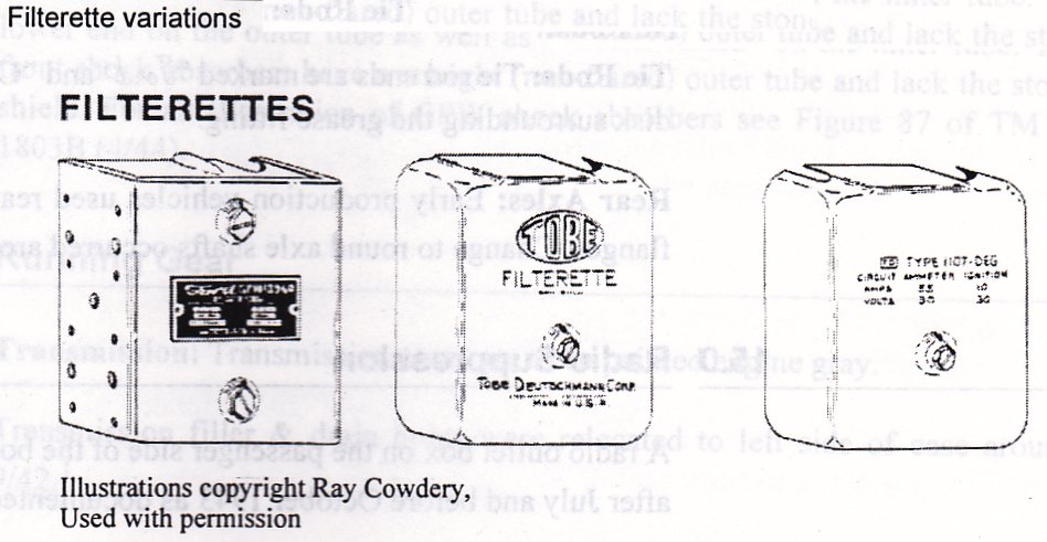
GPW's produced before 1944 incorporated a "Filterette" assembly mounted on teh firewall, under the dashboard. This consisted of several large capacitors in a steel housing whose purpose was to bypass radio frequencies occuring in the low voltage electrical system to ground. Several styles of filterette s were used in GPW's, three are illustrated below.
1/. Ford GPW-18960 w/2 slotted hex. screws (S7) retaining cover. Mfg. Sprague w/Ford tag. These have been found in vehicles produced in Summer of 1942.
2/. Tobe-Deutschmann 1107DE w/deep draw cover stamped "TOBE" with manufacturers info stamped near bottom. Cover retained by one slotted S7 finished hex. screw.
3/. Tobe-Deutschmann 1107DEG, similar to above w/o large logo and electrical specs on cover. This was parnumber GPW-18960-B.
4/. Tobe-Deutschmann 1107G (not shown) with friction cover and brass etched tag. Seen on 4/42 vehicles.
Updates below this line.
GPW-18960 Image -
Tobe-Deutschmann 1107DE
1107DEG Image - Jon Rogers
This Web Page Created with PageBreeze Free HTML Editor