|
REBUILDING THE ENGINE
- PART 2 -
- John Barton -
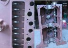
 The valve train goes in quickly. I have a rotating engine stand, but I
prefer a wooden bench with carpet. Small parts don’t bounce or roll away,
sometimes I want to put the engine on end, and in the beginning…it is
easier just to manhandle the block.
The valve train goes in quickly. I have a rotating engine stand, but I
prefer a wooden bench with carpet. Small parts don’t bounce or roll away,
sometimes I want to put the engine on end, and in the beginning…it is
easier just to manhandle the block.
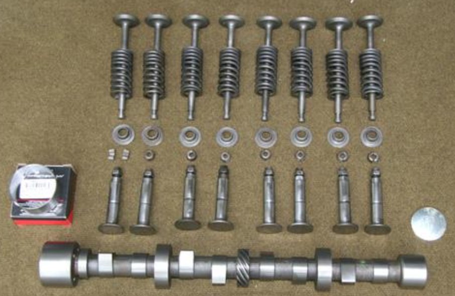
The valve train consists of the camshaft, the tappets, the locks, the
retainers, the springs, the guides, and the valves.
You can buy every piece brand new. I don’t replace unless it is necessary.
The camshaft turns at half engine RPM’s which is really slow by engine
standards. I have replaced some, but I’ve never seen one that probably
couldn’t be used…just lucky I guess. Part of it depends on how the oil
pressure was. On some engines, replacing the main and rods bearings will
cure low pressure. On some it doesn’t help at all…a lot of pressure can
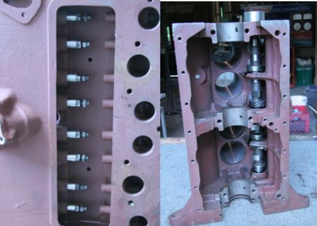
be lost at the cam. The cam has four journals with corresponding bearings in
block…the front one is replaceable; the back three are machined in the
block. The back three can be sleeved and re-bored. Ask your machinist to
check the iron ones…the replaceable one is usually around $12. Replace it!
The cam journals can be polished if they are pitted. The lobes for the
tappets are actually pretty sharp. You need to see a good one to compare. If
you don’t get a good feeling from the machinist…NOS camshafts are still
available. They usually need to be polished anyway from storage surface
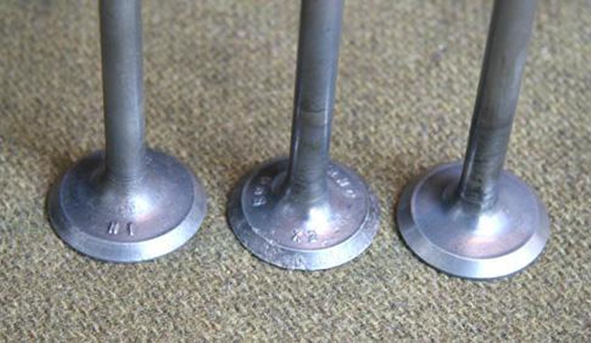
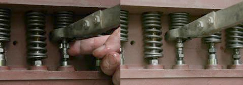
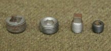
rust. The bottom surface of the tappets can be worn. If there is a
depression there, replace. If they just have a light circle pattern on
them… they are ok and turning properly. The top of the tappet is more
likely to be worn.
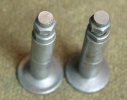
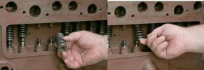
Notice the left one has a bowl shape from the valve stem hitting it. The one
on the right has been put on the valve grinder. It makes a new square
surface.
the right has been put on the valve grinder. It makes a new square
surface.
The hole in the block where the tappets ride are usually not a
problem…tappet is constantly splashed in oil, and there is a drain hole in
the valve chamber that feeds them also. The groove around the tappet is for
oiling the hole sides. Tappets that are .002 oversize are available…I have
never used them. I don’t know if the hole needs to be reamed or if that is the
wear.
The only problem with the locks and retainers is that you loose one!! If you
only need one, let me know. If you ever do a valve job with motor in
jeep…You will learn to put a rag in the valve chamber after the first key
falls into the crankcase!!..I have never done that!!
For the springs I just line them up.. all the same height.. no leaners.. ok. I
do check with a square, and look for pitting, breaks etc.
Once in your jeep's life, you will have to buy a new valve (two actually since
that’s the only way they come). You need it to check the guides. If you
take it to machine shop, he has pilots and can check for you. He will do
that if you are having seats ground. All the manuals have pages about
replacing valve guides. If the guides have been rusting in the block for 60
years.. it is not so easy! But, it is also not necessary. You put the new
valve in the guide. If it rattles, you need to fix. If it barely moves side
to side.. it is ok.
I’m sure there are specs and you can measure deflection with dial
gauge.….??
You can buy new guides. Pulling them out the top as instructed is not easy,
the machinist will probably just drive them out the bottom. Then you have to
set the new ones to correct heights…they are different for exhaust and
intake. Too much trouble and money.
The first alternative is to have them knurled. A special tap is put through
them raising metal. Then they are reamed back to original size. Some machine
shops believe knurling is better since there are now grooves that help oil.
I have done that. The machinist I used for this engine prefers putting in
bronze inserts…he claims it is just as fast as replacing or knurling. The
guides are drilled, the insert is put in, and it is reamed. In this engine
the guides where good, and I had enough valves around to grind some good
ones. I wire wheel them to remove any carbon on top or on stem. I also chuck
them up in my lathe and polish the stems with 1200 grit emory paper if
necessary.
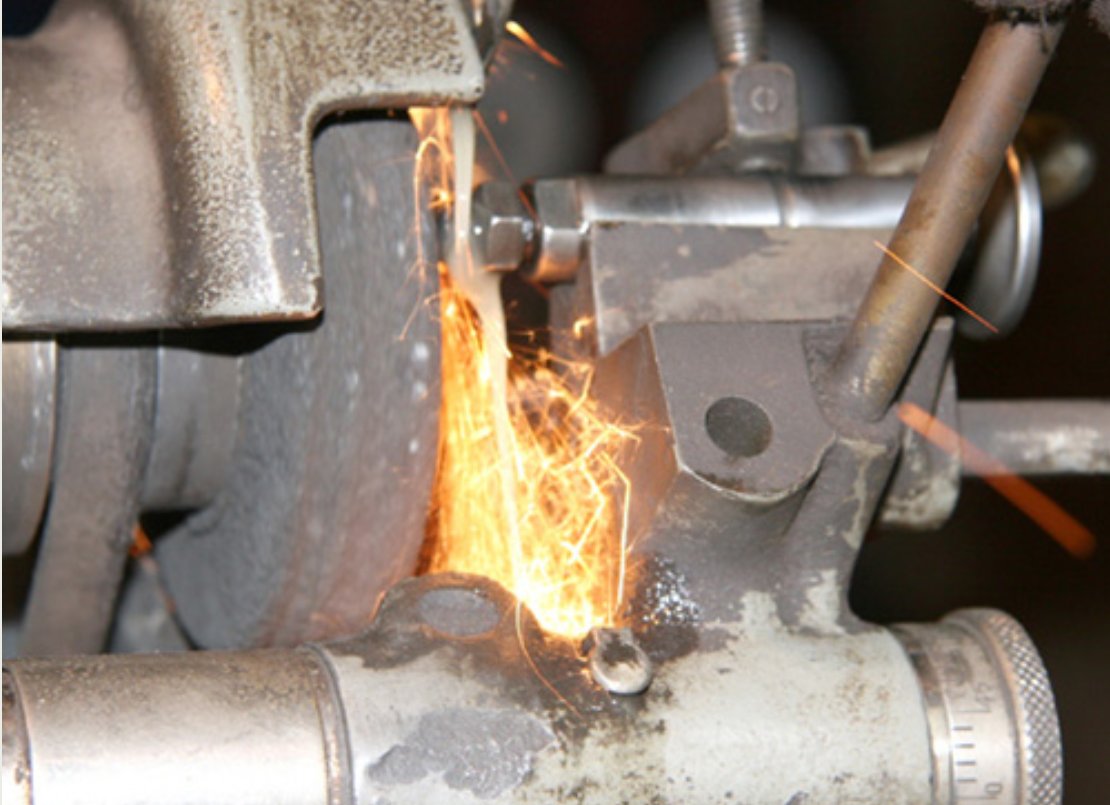
 I have a valve grinding machine. If you are nearby and want to grind some
valves, come on over! The valve surface is ground at 45% (not exactly) to
match the seat in block.
I have a valve grinding machine. If you are nearby and want to grind some
valves, come on over! The valve surface is ground at 45% (not exactly) to
match the seat in block.
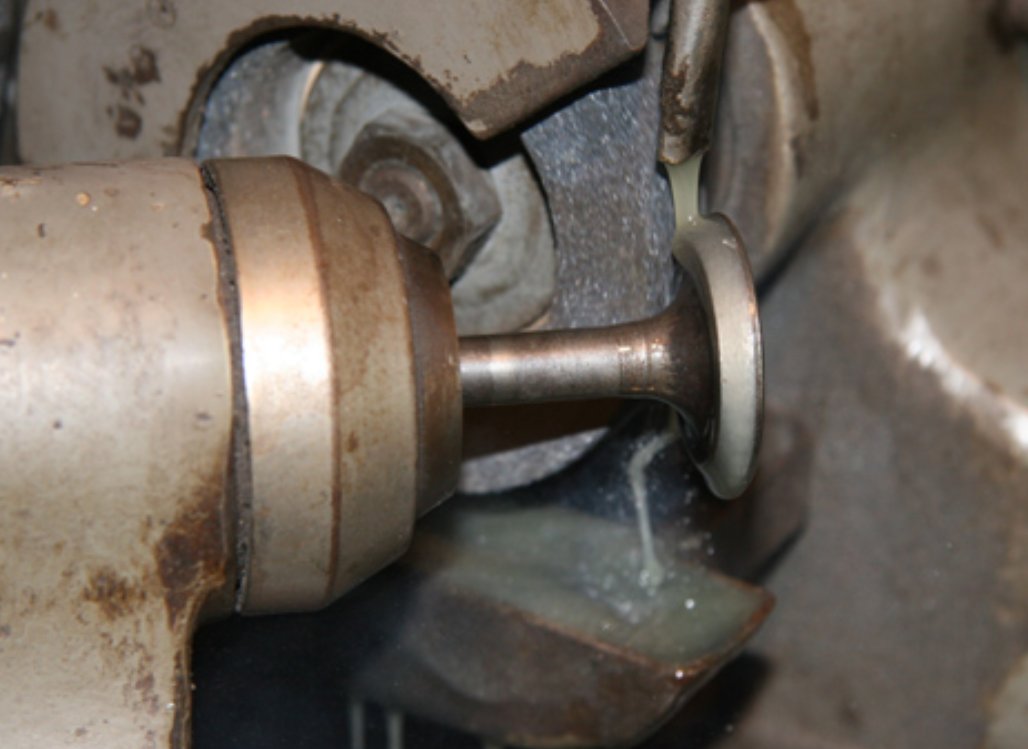
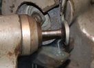
The bottom of valve stem is ground square
T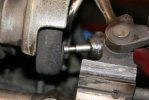 hen the bottom of the stem where it contacts top of tappet is chamfered. It
takes about two minutes per valve. hen the bottom of the stem where it contacts top of tappet is chamfered. It
takes about two minutes per valve.
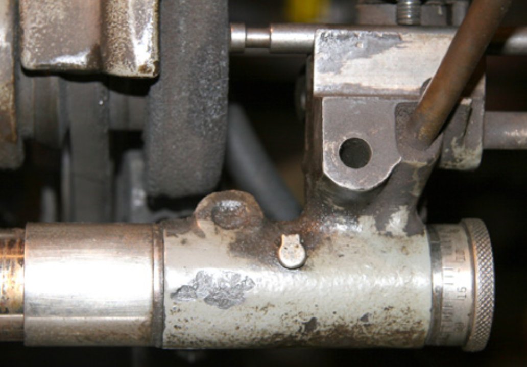
When you grind valve face, it now sits down further in block. When you
square the stem, you are supposed to take off the same corresponding amount
that the valve moved down. In the old days…machinists would measure valve
height difference with run out dial, then use micrometer on stem grinder
(you can see it in picture- to take off same amount). But I have also faced
tappet!!...so they are even further apart. Fortunately these tappets have
more than enough adjustment to make up the differences- so it is not that
much of a concern. Besides, you only take the smallest cut.
I have seen a lot of discussion on the G about hardened valve seats,
satellite valves, leaded gas, etc…I don’t know…? It is probably a good
discussion. If you have the money.. it can’t hurt. I don’t think it is
necessary with this motor. I do use lead substitute in my gas when I drive a
lot. I have a valve seat grinder. It is a big drill with pilots and stones
to grind the seats. You dress the stones, then put them on pilots and spin
them in seat with pilot inserted in guide. Check the picture in part one. I
asked the machinist to do it because of the repairs. He told me I could have
done it as usual, but he did have a special stone to grind the hard pins. He
also did not think this engine needs any special valve seats. There are two
cuts- one is 30 degree angle for relief…and then the 45 degree to actually
contact valve face. The amount of contact has to be pretty 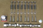 precise. Too
little and valve will break or distort from pounding. It can overheat
because there is not enough contact to transfer heat away. Too wide and it
will leak because there is too much surface area. The spring can’t hold it
down enough. Just a hair over 1/16th is what I use. precise. Too
little and valve will break or distort from pounding. It can overheat
because there is not enough contact to transfer heat away. Too wide and it
will leak because there is too much surface area. The spring can’t hold it
down enough. Just a hair over 1/16th is what I use.
When I have all the parts like I want…I lay them out. It makes assembly go
very quickly. � hour or less.
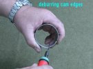
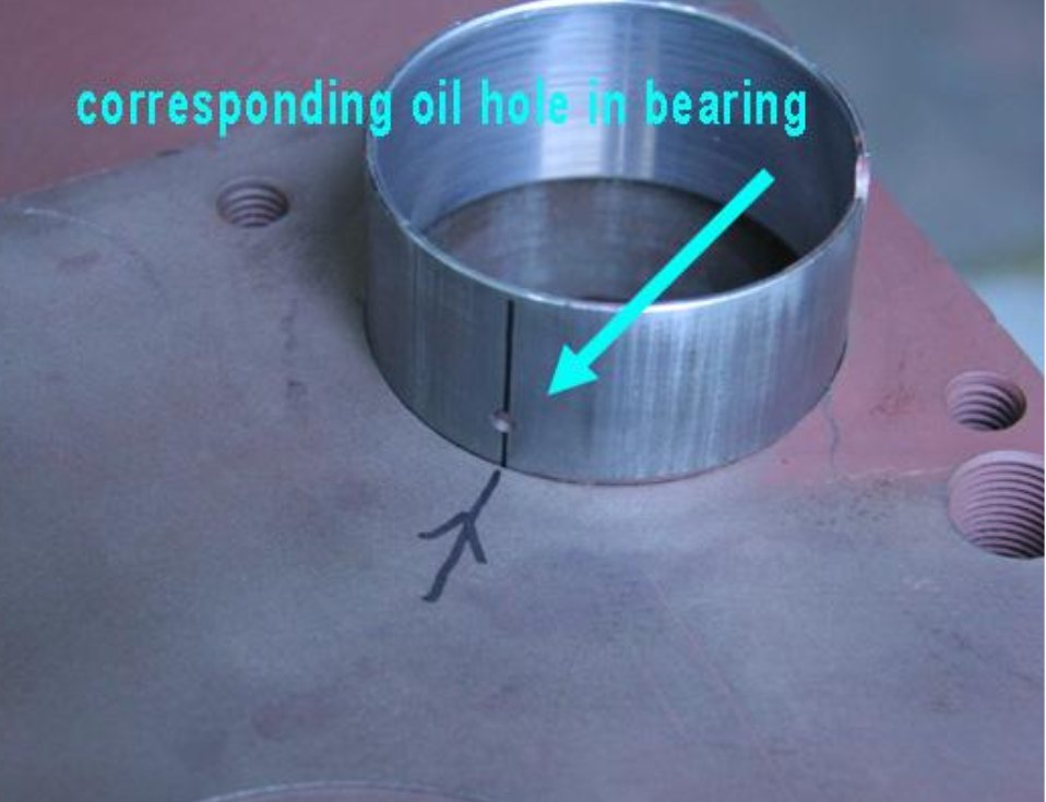
First, I de-burr the bearing. It is bored straight through. I just chamfer the
front edge, it won’t catch when I install the cam.
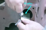
Next, I install it. I put a layout line from cam bearing oil feed hole to
the front of the block.

 MISSING PHOTO MISSING PHOTO
Then, gently smack it in with bearing insert tool. You don’t absolutely
need this tool; a flat plate will work if you line it up correctly.
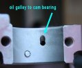
Put some compressed air to galley on front main bearing, and you’ll know
if you lined them up correctly. I do not stake the bearing.
I grease the tappets. I use STP mixed with assembly lube…very sticky! I
have the block upright on it's back end. This way you don’t have to clip or tie
them in up position to install the
cam.
MISSING
PHOTO
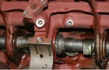
With tappets all in up position, lube the cam and gently drop it in. Guide it
through with other hand to avoid hitting or scratching the bearing surfaces.
After it is in, I just lay block down in normal position. I put cam gear on
front with a couple of the bolts so I can turn cam to raise and lower
tappets. They are now riding on the camshaft lobes.
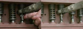
Now, put a retainer in bottom of spring. Close coils on spring go up against
block. Put spring over part of guide that sticks down. You can usually just
use your hands to snap spring over tappet. If not, just pry it over with
screwdriver. You need to turn camshaft so tappet is in lowest position.
MISSING
PHOTO
When all the springs are in, install valves from the top. The intake and
exhaust valve are different. They are usually marked.

If not the intake has the larger head. 4 intakes, and 4 exhausts. If
you’re not familiar with the layout, get manifold. Check picture on first post
for labelling of intake and exhaust ports. But look at the manifold, and you can
figure it out.
Ex-In-In-Ex-Ex-In-In-Ex front to rear (same either way) 2 per cylinder, one of each.
cylinders are number 1 2 3 4- from front to rear.
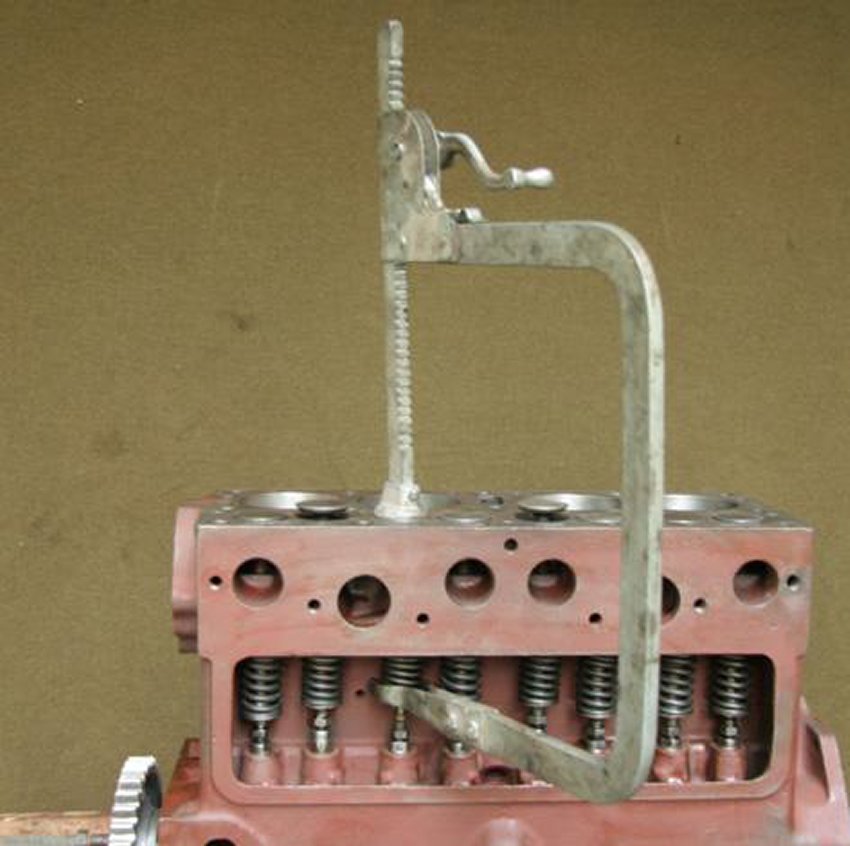
Next, the spring compressor
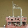
This is one from sears that I have had since …?
It ratchets the spring up. I put the greased keepers in place. Then let it
down!
You need to turn cam again as you go, to do each set, to lower tappet. There
is a place on the cam where both valves are closed. Pretty slick!
Valve train is now in place. I have been cleaning, lubing, etc as I go. Now
I want to close up the oil galleys. The main galley runs along bottom in
crankcase. Several passages are drilled to it and through it, to feed oil
pump and bearings. The outside holes don’t serve any function, but are the
result of the machining to make the passages. Here is one concession to
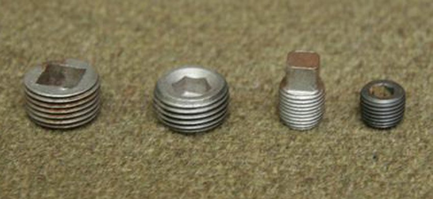
modern parts. The two 3/8 pipe plugs at front and rear of block originally
had recessed square drive…it is not a standard size. I replace with a hex
head. You must learn the difference between standard threads and pipe
threads. Don’t chase or clean these galley plug holes with standard taps.
There are pipe taps…but a good bore brush is fine.
I bore brush all the galleys one last time, compressed air, then plug with
Teflon sealant on threads.
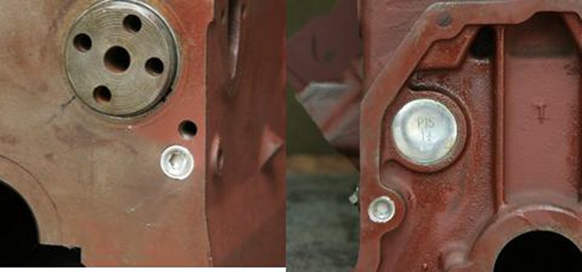
I also install the cam bore back plug now. It is a cupped disc. Put a 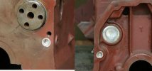 little
sealant on edges, insert it in place, and smack center to expand edges. You
are supposed to use a smooth rounded surface like a ball pien hammer. I
don’t like striking the face of one hammer with another, so I use a large
brass drift with smooth face. little
sealant on edges, insert it in place, and smack center to expand edges. You
are supposed to use a smooth rounded surface like a ball pien hammer. I
don’t like striking the face of one hammer with another, so I use a large
brass drift with smooth face.
The original plugs for the passages inside the crankcase were a square
socket drive. See picture. I replace those with modern hex drive, because
one easier, two…there are mentions of interference with the counterweights
in some manuals.
The old style plug could get hit by crank. I do use the original ones on
outside of block to keep original appearance. These passages go up to two
center cam bearings.
MISSING PHOTO
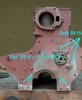
The two other outlets are for oil pressure gauge and to oil filter. The get
brass fittings, but they are also pipe thread.
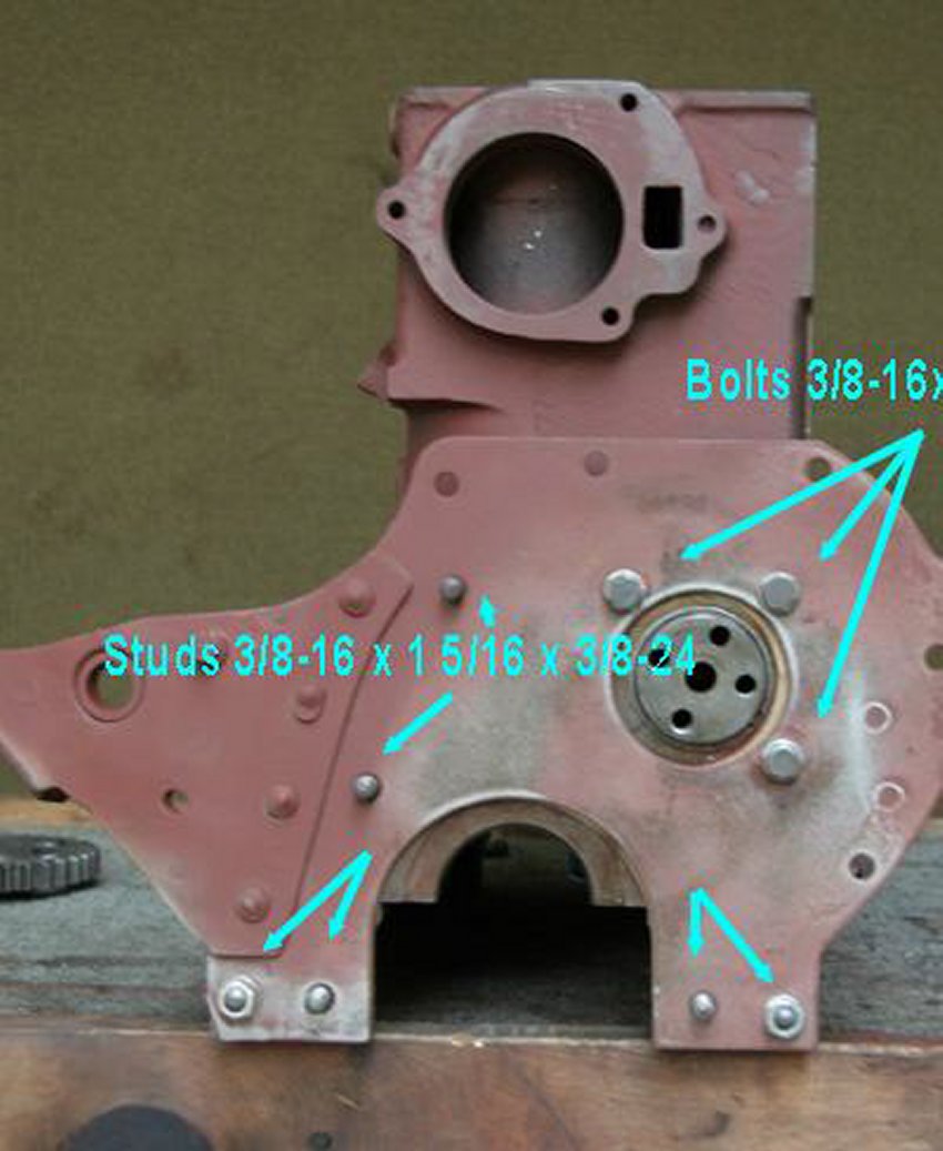
I put on the front plate now. It needs to be in place for crankshaft and cam
gear. I have labelled the bolts and studs. The stud dimensions mean that it
is threaded course on one end and fine on the other. The middle number is
overall length. The course end goes in the block, the fine threads are for
plate and timing cover.
If you use another method, or have better idea/tools- please post.
Next is installing crankshaft and pistons
Home
John Barton's Engine Rebuild 1 3 4
g503.com
|