|
REBUILDING THE ENGINE
- PART 4 -
- John Barton -
In a previous part, I mentioned that it was not necessary to know the
4-cycle engine theory to rebuild this engine. It does, however, help a
little to understand some of it when dealing with setting up the timing. In
a 4 cycle (also called 4 stroke) engine, the usual description of this cycle
starts with: the intake, then compression, then power, then exhaust stroke.
During these 4 strokes the crankshaft rotates twice.
Turn the crankshaft clockwise, looking from front, (nut on front/or with
flywheel bolts) until the front- #1 piston is at the top. #4 (back) is also
at the top.

Both are at the position called TDC- top dead center. You don’t need to
worry which stroke is involved at this point. Until the crankshaft and
camshaft are in time, just realize that the crankshaft turns twice during
the four stroke cycle, and that the camshaft turns once- (half speed).
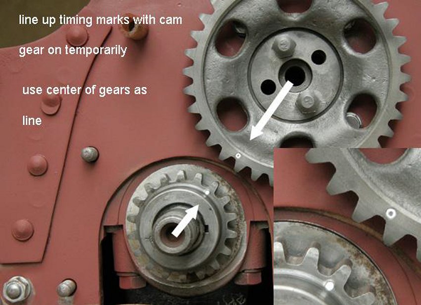
When the cam gear is installed- temporarily as in one of the pictures below,
you can see the relationship. Cam gear is twice as large as crank sprocket.
When connected by chain, the crankshaft must turn twice to each cam
revolution. This is because while the pistons must go up and down twice (2
crankshaft revolutions) to complete the 4 stroke cycle, the valves must only
work once for each cylinder (1 camshaft revolution) during the 4 stroke
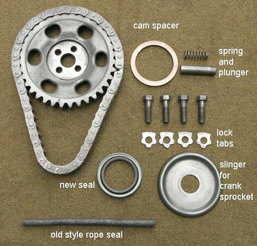
cycle. I have all the camshaft parts laid out.
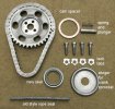
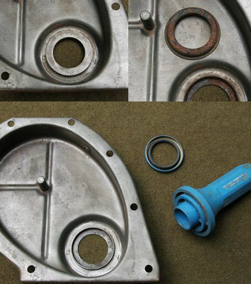
Both types, rope and the newer modern timing cover seal are shown. When the
old steel retainer is removed, the asbestos rope seal must be removed. Clean
up the surfaces and install new type with seal driver…a large ˝ drive
socket that fits diameter of seal, also works.


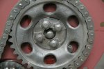
Note the dots on crankshaft sprocket and on camshaft gear, turn cam gear
until they are lined up. Take camshaft gear off, lube camshaft spacer/thrust
washer, and put in place behind gear. The holes in front of camshaft are
offset- the gear will only fit one way. Slip chain over sprocket, then place
chain over cam gear- keeping it in the same position…watch dots and
camshaft holes, and wiggle gear until bolt holes line up.
When in time, the timing marks on both gears will be in line.
 MISSING PHOTO
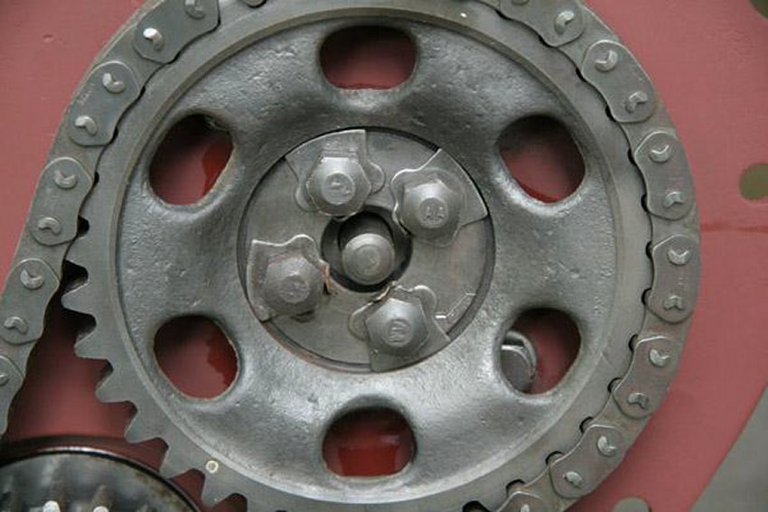
Place special washers- have a curved surface that fits in cam gear- and
bolts, and torque them to 35lbs. Bend the tab on the washers over.
Place spring in camshaft hole, then thrust plunger. These provide thrust
when cover is installed to hold camshaft in place. Put oil slinger on
crankshaft in front of sprocket. Install timing chain cover. This probably
wont be coming off, so I do use some sealant.
I labeled the bolts sizes. 3 are 3/8-24x3/4, the last is 1”- doesn’t
specify where the longer one goes, but- two of the top bolts also get a
clip- one holds the oil line that feeds the filter, the other holds the
steel fuel line going to fuel pump. It may also be for the different front
(reinforced) mounting plate? While the other bolts for oil pan are 5/16-18
x11/16, the four across the front are only x1/2”. The parts books are a
little confusing concerning oil pan bolts. They list 4 different sizes, but
they add up to more than required, and only two sizes have descriptions of
where they fit. The short ones in front are so they don’t pierce the
timing chain cover. You need to use a little care here with gaskets. The oil
pan gasket is already in place, when you put timing chain cover on- make
sure you don’t push pan gasket out of place. No pulley guard for now
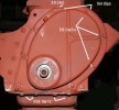
I put the flywheel on now because it helps visualize timing with the
markings. Put back engine plate in place. Two bolts thru the flanges will
hold the plate temporarily. Bolt up flywheel. Two of the bolts are dowels or
shouldered. Make sure timing marks are visible in timing hole. It will go on
in two positions-correct and 180 degrees out. Torque to 40lbs.
Now that everything is hooked up, you can see the valve timing relationship.
Turn the engine clockwise (viewed from front again). As #1 travels down,
notice that the intake valve opens. #1 is on the intake stroke. Watches #4,
as it travels down, both valves are closed. #4 is on the power stroke.
Ignition has just fired in #4. It actually occurs just before TDC- takes a
few milliseconds for explosion of fuel-air mixture, and for the power to
develop that pushes piston down.
This may be a little confusing, because most manuals, etc. deal with #1 when
setting ignition timing and installing oil pump. However, we have just set
the crank-cam timing and #4 is on ignition? Easy to fix…!
Before that, set the valve clearance. If you turn crankshaft another half
turn again, when #1 starts up, it is on compression. When it reaches TDC
again, both valves are closed. This is when valves for that piston are
adjusted (when each piston is TDC for ignition). The tappet is not on a cam
lobe, and valve is held closed by a spring. Adjust clearance using two ˝
inch open-end wrenches. Special thin tappet wrenches are available, but not
absolutely required. The clearance on chain drive engines is adjusted to
.014 or 14 thousandths. You need a set of feeler gauges that has a .014
piece. Since the tappets and stems have been ground, you may need to play
with adjustment to get them close. Hold the tappet with one wrench on the
flats. The adjuster is like a regular bolt. Turn right (clockwise /in) to
turn it down into tappet, which opens/increases clearance. Turn left (counterclockwise/out)
to close/decrease clearance. Valve clearance is important. Too much and
engine will clatter as tappet hits bottom of valve stem. Too little and
valves will open too soon.
It usually takes a few times to get exact adjustment. You adjust, try
feeler, adjust, try feeler again, etc. The clearance is ok when gauge slides
with a little resistance.
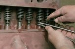
In the picture, you can see that I hold two wrenches in one hand, hold
feeler with other. After major adjustments get the clearance close, by
changing which wrench is on top, I can increase or decrease clearance by
squeezing wrenches together. I adjust to a loose .014, then make final
closing while sliding feeler gauge between tappet and valve.
The firing order is 1 3 4 2. Turn crank half turn again until #3 is coming
up to TDC, both valves closed, … adjust them. Same for 4 and 2- half turn,
adjust. Try to get clearance exact now. Normally, you will need to adjust
again after engine is run in a few hundred miles. But, sometimes it is not
necessary.
After #2 is adjusted, another half turn should put you back at TDC for #1
with ignition. This is where you need to be for final steps. If not sure,
turn crankshaft until you have seen all the strokes:
Piston going down with intake open- INTAKE
Piston coming up with both closed-COMPRESSION
Piston going down with both closed- POWER
Piston coming up with exhaust open- EXHAUST
You want #1 at TDC, both valves closed, at ignition. This is important
because oil pump and distributor must be installed in time to crankshaft and
camshaft. You can actually install oil pump in any position, install
distributor, and wire from wherever the rotor points, to spark plugs, in
firing order. But, for the sake of future jeepers and our kids…. lets try
to make all jeeps match the books!

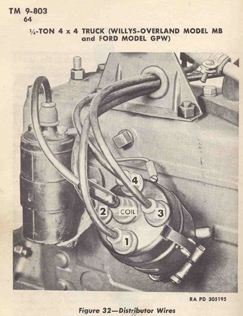
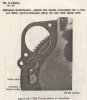
Note how in TM9-803, the #1 spark plug wire is always at 5 to 5:30 clock
position, looking down on distributor. OK, for the second photo- you have to
turn it upside down and imagine looking at the distributor on the right
side of the block! Strange- manuals refer to engine sides as if you are
sitting in jeep- but describe rotation as your looking at front of engine!
This question has come up on G503 many times. When the oil pump is removed,
it must be re-installed in time! If you have seen these discussions, there
is always a question about finding TDC for #1 at ignition. You can’t trust
the flywheel, whistle devices, thumb in #1 spark hole, etc. With head or
valve cover off, you should be able to see and establish #1 TDC exactly.
When oil pump is installed, the drive gear engages with the gear on cam.
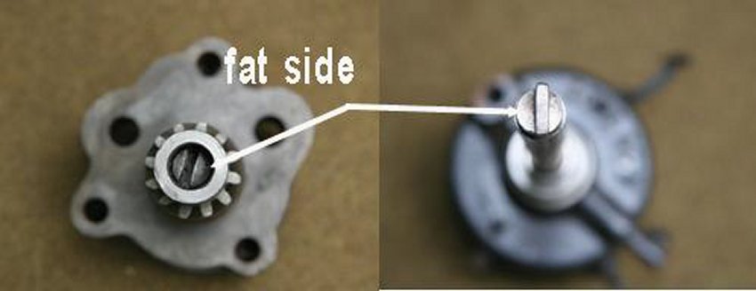
When the gears engage, oil pump turns- The top of gear has an offset slot.
So, you need to turn it back, engage gears, with slot winding up in correct
timing position. The bottom of distributor shaft has corresponding key, with
offset, that fits into slot. The oil pump drives the distributor. Look down
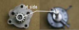
through distributor shaft, slide oil pump part way onto mounting studs. With
long screwdriver turn oil pump gear so slot points to 9:30 clock position
with fat part on top. When oil pump is pushed to final position, the gears
engage, and it should turn to 11/11:30 with fat part still on top.
Put one nut on to hold oil pump in position. Install distributor, you need
to wiggle it to get key into slot (remove anti rattle spring for this part).
If oil pump timing is correct, the rotor on distributor, will point to
5/5:30. Because of offset, it will only engage in one position. If not
correct…drop oil pump and adjust gear position accordingly. Try
distributor again until rotor winds up pointing to 5/5:30.
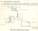
Crank, cam, oil pump, and distributor are now all in time! You can wire
spark plugs just as shown. As I mentioned above, you can install oil pump
and distributor in any position and wire spark plugs from wherever rotor
points. Just go around distributor cap counterclockwise in firing order. But
all manuals show #1 firing position as 5/5:30, so we should do it for
uniformity.
I’m not making final distributor installation now because of painting etc.
When you do install distributor, turn body so coil-wiring terminal is near
11 o’clock. If you haven’t turned engine…rotor will still be pointing
to #1. With ignition mark on flywheel lined up with marks on cover,turn body
clockwise until points just open. Tighten distributor clamp- should be close
enough to get engine started…!
In the final post, I’m going to show all rest of the bolts and plugs, etc.
As I mentioned, this engine is replacing a MB motor in a GPW. For this post.
this will essentially be a short block with remaining parts coming from
other motor.
Home
John Barton's Engine Rebuild
1
2
3
g503.com
|