|
REBUILDING THE ENGINE
- PART 3 -
- John Barton -
The main and connecting rod bearings used in the jeep engine are two semi
circular halves called inserts. When installing these in the block and
connecting rods, some care must be observed. If there is good clean oil, and
the engine is not abused, they can last a long time. As long as there is an
oil film, the rate of wear is slow. Grit or dust getting into the oil,
either through the carb, or from installation, can ruin a bearing. In my
pictures, you can see that I use a lot of assembly oil. But, by having
everything ready…I get it closed up quickly. I wipe up excess- no oil
should get on threads or bolts…to get proper torque, they need to be clean
and dry. Wipe down all bearing surfaces, there should be nothing behind an
insert.
1

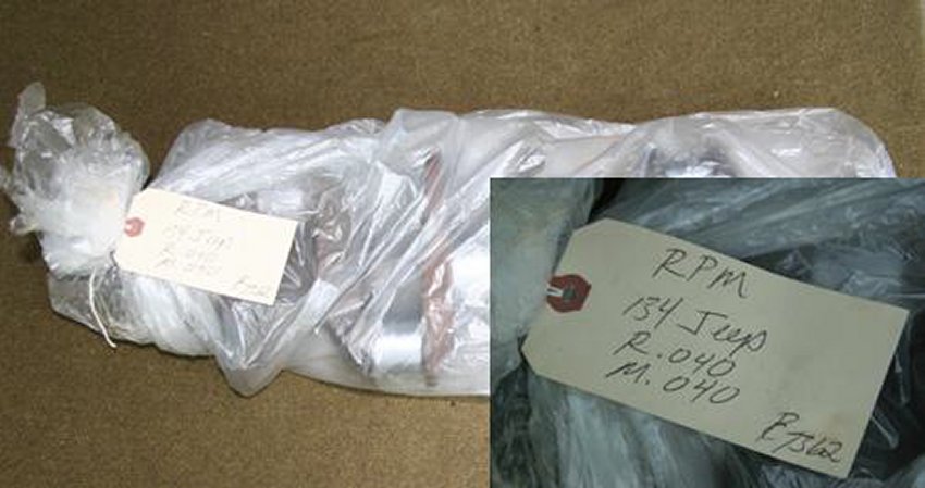
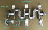
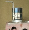
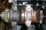
This is how the crankshaft comes from the machinist. Leave it in the bag
until ready to install. The journals are precisely ground and polished.
Scratches, etc are no good, and they will rust in a minute. The tag
indicates that this crank was cut .040 undersize on mains and rod journals.
From old inserts, you can see what old size was. This crank was .030/.030.
So it was cut the minimum, increments are usually .010.
2
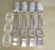
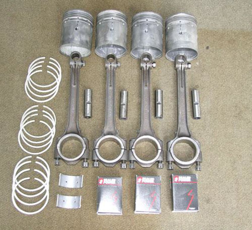
As with the valve train parts, I lay out everything. I assemble pistons
first.
3
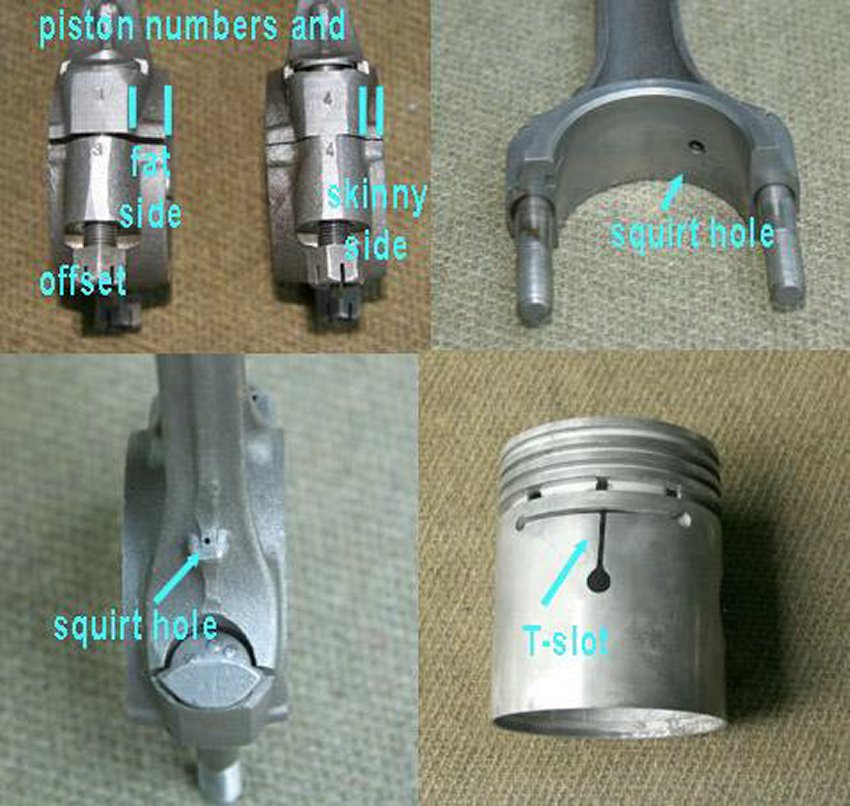
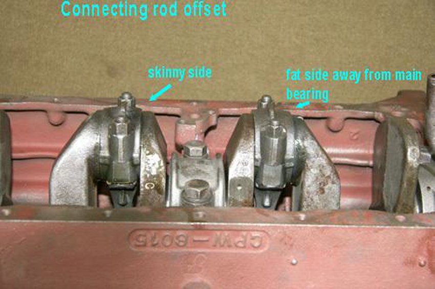
The pistons must be assembled with T-slot and squirt hole in correct
relationship. They must also be installed in cylinders with offset in
correct relationship to main bearings. The connecting rods may be numbered,
check during disassembly. The numbers, letters, dots, etc. can be on either
side. You can’t always use them as a reference. Cylinders are numbered
1-4- front to rear. Often one rod has been replaced. So, you must use
correct assembly and offset to install. As shown in part one, pistons often
have an arrow on top pointing to front. Use the arrow, slot, squirt hole,
and offset to check that pistons are assembled and assigned correctly.
4
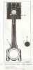
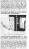
Scan from CJ manual that shows correct piston assembly.
5
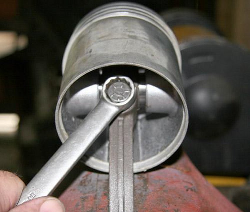
These new pistons came with wrist pins. Place connecting rod in vise leaning
away with lock bolt on top side. Slide wrist pin into piston, lining up slot
with bolt. Place piston on connecting rod and finish pushing wrist pin
through. The torque setting for the lock bolt is 35 lbs. I don’t have a
torque wrench that will fit up there. I snug it tight. You can use a
crow’s foot on a torque wrench and do the math etc. I also lube each pin
in the piston.
6
7

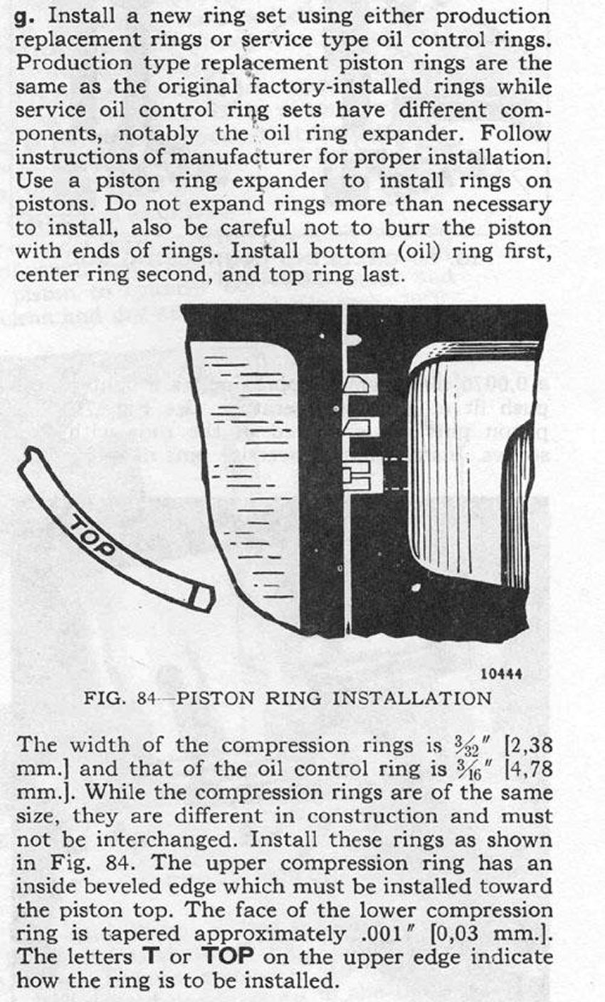
I leave piston in vise to install rings (straighten it up). Rings come in
different styles, but are generally same shape. There is usually an
instruction sheet, or the packages are labeled to show which ring goes in
which groove. The widest is the oil ring, it can be one piece or three
pieces, and it goes on first in bottom groove. Two different compression
rings go on next, see picture and explanation from scan. Most rings have a
dot or TOP, but you can figure it out from shape. The ring expander tool is
cheap. Rings are brittle and will snap if twisted or opened too much, Open
only enough to fit over piston. No ring goes in top groove. If using old
pistons, clean all grooves. Use an old ring, break it, or buy a groove
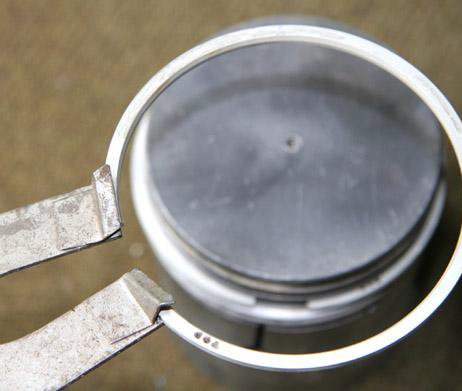
cleaning tool. Most manuals show measuring the ring gap, and the play in the
groove. I check a few of the rings by installing a piston head half way down
a cylinder, inserting a ring on top and seeing that they are close to specs.
I’m using new pistons, new rings, and a machine shop I trust. I do not
measure every single ring.
8

9
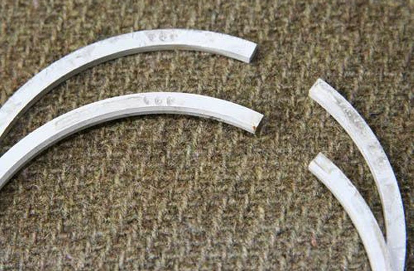
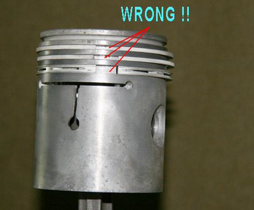
The gaps in the rings must be staggered around the piston- 120 degrees from
each other- do not line them up as in picture.
10
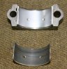
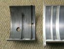
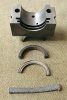
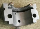
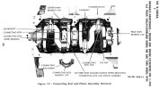
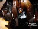
Picture of new rod insert in a rod cap. There is a notch that must be lined
up. Inserts come with a spread, so it will stay in place. To set it in
place, gently tap it on a flat surface. As mentioned above, it must be clean
behind insert. Most modern inserts have two holes in both halves, one of
them lines up with squirt hole in connecting rod top, not necessary in cap.
The old insert show the worn bearing material flaking away and scorched.
11

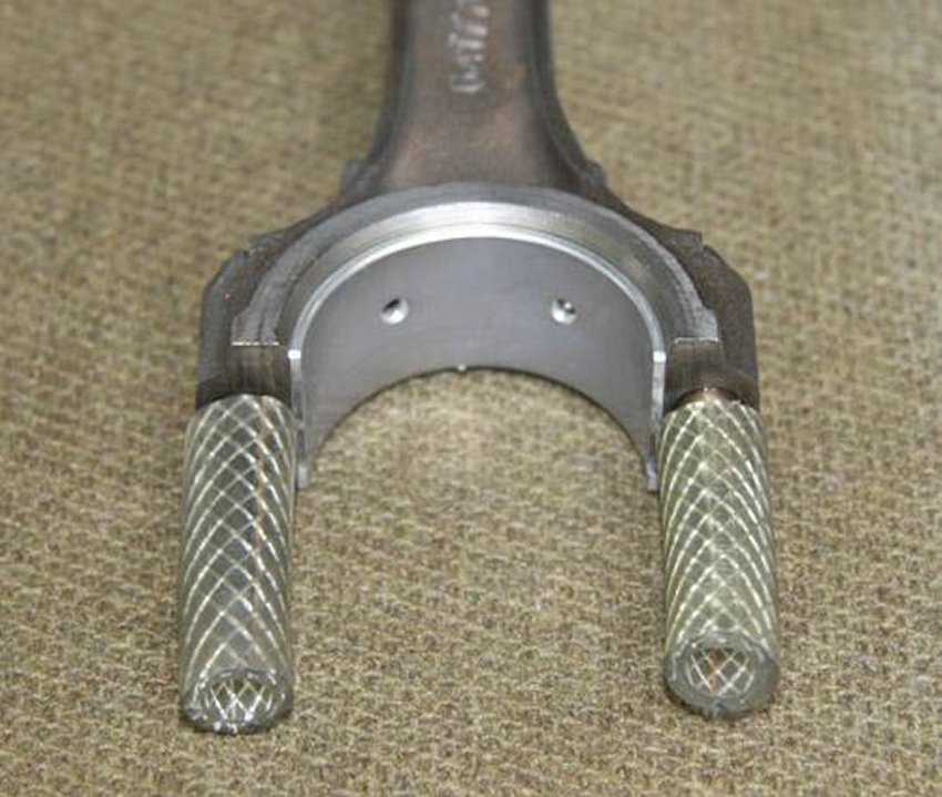
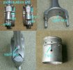
Install upper shell (interchangeable) in connecting rod. Notch and squirt
hole have to line up. Connecting rods should have been cleaned, but check
that squirt hole is clear. Cover the bolt heads with cut off piece of
3/8’s rubber hose. The fit down the cylinder is tight, big fat pieces of
hose will not work; these are part of an old air line.
12
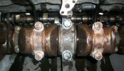
I lay out the crank with inserts. I’m pretty liberal with the assembly
lube. Buy the time I close up the crank case, every galley in block and
crank will have been squirted a couple of times. Wipe up excess when
installing caps and bolts etc. Clean threads for torque!
13
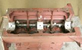
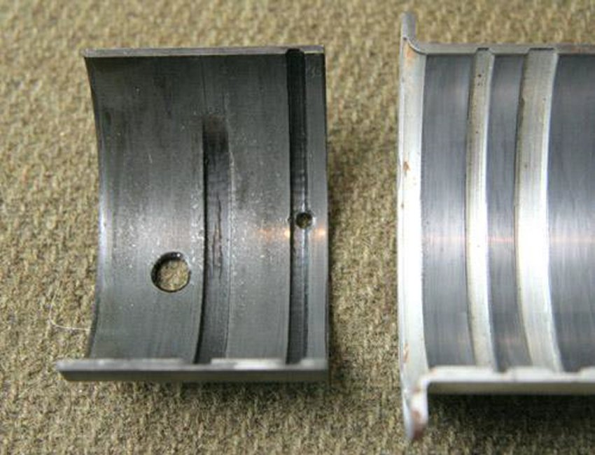
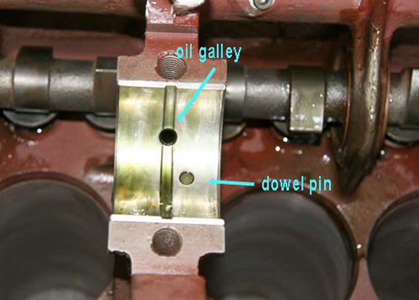
Put the upper shells in the block, some brands are labeled with a U or L.
The front bearing has a flange- to control thrust. The rear has two grooves.
So you can figure out which goes where by lining up oil galley holes and
dowel pins. In earlier pictures, the dowel pins where in place. They usually
don’t fall out. Clean around them; make sure bearing surface is clean and
dry.
14
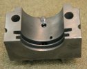
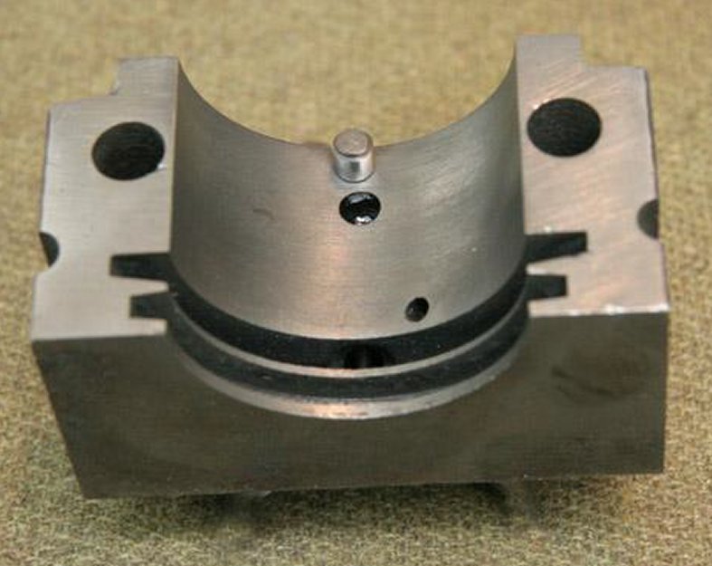
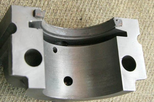
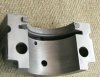
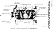
Here is a picture of rear main cap with dowel pin out. The front cap does
not have a dowel pin, the flange prevents the bearing from spinning, and
there should be five dowel pins.
15
Picture of old insert. Again, you can see the flaking metal.
16

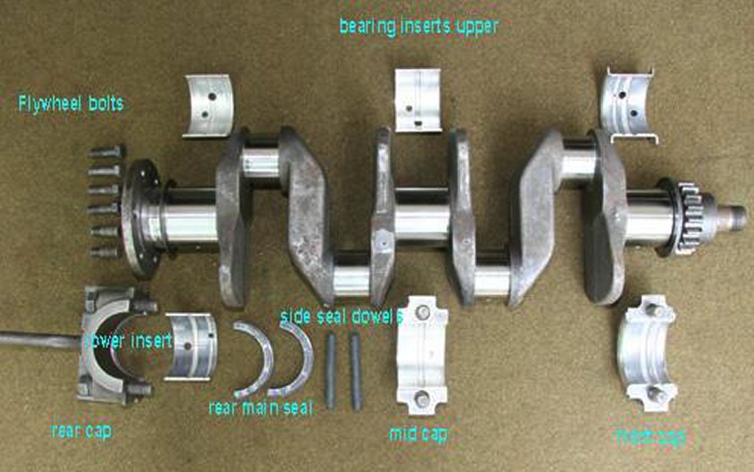
Spread some assembly lube evenly on the inserts in the block and the caps.
Put the rear main seal in place (pictures below), lay the crankshaft gently
in the block. Put the flywheel bolts in crank rear flange. One you put the
rear cap on…you won’t be able to get them in! Just before I put the caps
in place, I squirt more lube down the crankshaft oil galleys. The assembly
lube, with STP will stick and stay until engine start-up.
17
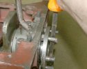
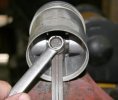
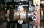
This is how I turn crankshaft. Hand tighten the main caps, turn crank one
complete revolution. From now on, every time you tighten a main cap bolt,
turn the crankshaft one complete revolution. I start with middle cap, torque
to 50 lbs- turn! Either one of the other caps-turn! Last cap-turn! The first
time you do not turn for each tightening, if there is a problem-it will
bind, and then you need to start backtracking to find the problem. Now
torque to 65 lbs, again, turning between every bolt. You can put the front
crank nut on and use a ratchet and socket to turn crankshaft. Either way is
fine. When all the caps are torqued, and all have a lot of assembly lube,
you should be able to spin the crankshaft with one or two fingers on a
regular � inch drive ratchet on the front nut. Note the rubber dowels that
fit in the drilled hole between cap and block. Just before putting pan on, I
coat these in indian head shellac and insert, the pan compresses then to
seal. I also use a little on rear cap mating surfaces.
18
19
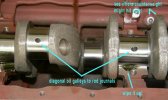
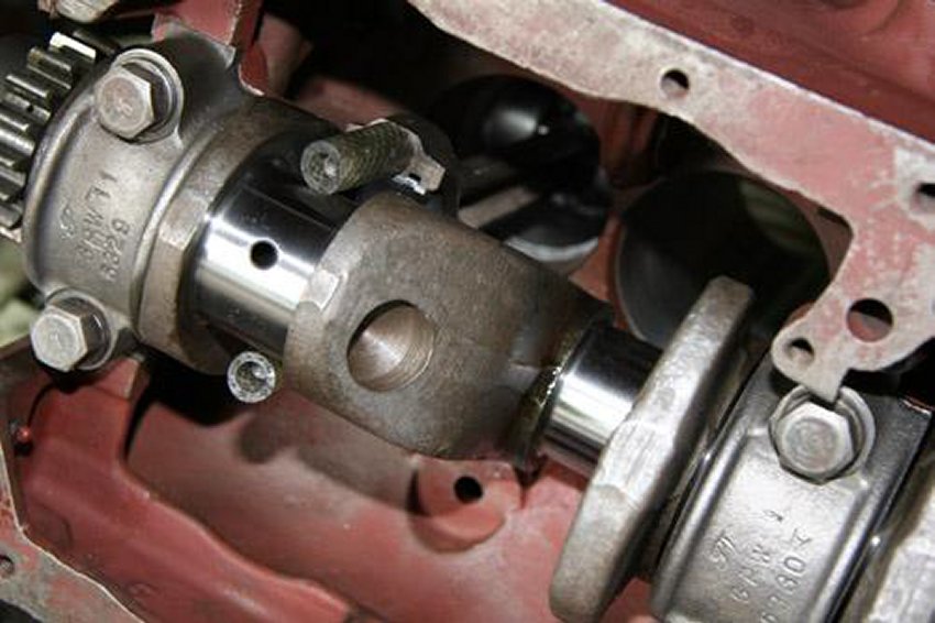
Picture of lube on journals, spread it out. Picture of diagonal oil galleys
in rod journals. I always squirt more oil down because of turning, plus as I
said a few times now…I want all the parts covered with assembly lube when
I start it for the first time.
20
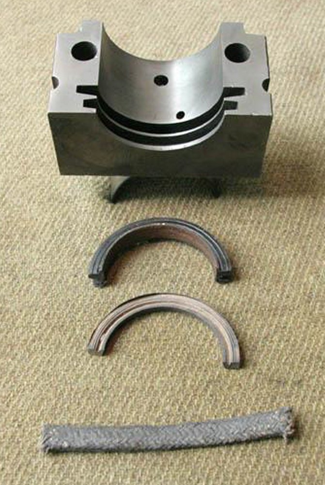
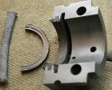
Picture of the three types of rear main seals. The rear main cap has a large
groove that the oil slinger on the back of crankshaft fits into. There is a
drain hole there for oil to flow back to sump, make sure it is clear. The
smaller groove toward the back is for the seal.
21
Picture of the asbestos rope type seal. Still works, I have used them, they
need a little care and attention when installing.
22
Picture of the rubber seal that was used for most of the service life of
jeeps.
23
Picture of the modern, metal supported, wider rubber/neoprene seal that
comes in most new gasket sets. I have seen or used them all. They work
equally well, the newest one is more forgiving of a rough or worn surface on
the crankshaft.
24
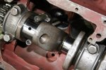
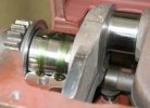
Main caps installed and torqued down with first piston coming in. For
crankshafts, many manuals show checking clearances with plasti-guage, etc. I
use it, but more to check working engines to see why or where oil pressure
is going? Again, This is new bearings, new crank, and a machinist that I
trust. The front gear sprocket stayed on this when it was ground, so I did
check the endplay per the books. It was ok. The rubber on the bolts keeps
them from scratching journals, but you still need to guide them by hand.
25
The ring compressor is a ratcheting sleeve that pushes rings into grooves so
that assembled piston can be inserted. Use a wooden hammer handle to knock
them down.
Wipe cylinder walls clean, use assembly lube on rings and compressor before
tightening it down. I still have the block on a wooden bench, but you might
find the engine stand easier. I put all pistons in from top just so rings
are in. Then with block on side, I can reach and pull rods into place or
control them while I knock from top. Do 1 and 4 together, 2 and 3…so the
journals are up or down together. Just before putting connecting rod on
journal, more lube. Squirt in galleys and rod cap, then snug it in place.
The torque for connect rod nuts is 50 -55 lbs. I do it in 35, then 50 lbs
steps. Again, rotate crankshaft a complete revolution between each step, and
between each cap. As you connect more pistons, and with the added resistance
from the rings, the crankshaft should still spin.
You should not need to push hard. If, on one of your tightening sequences,
it does bind,
you have problems. I once got a set of rod bearing with one odd size out of
the eight!. I wasn’t turning between every nut or bolt….darn! There are
other things that can happen.
A bent crankshaft is usually picked up by the machinist. But, bore mis-alignment
on the main bearings has happened. Old engines take a set, fatigue, over
heating!!
26
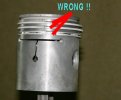
Two scans from manuals, the first one is from 1803A, and is wrong! Every
other picture and description is fat side away from nearest main bearing. It
took me a while to reconcile this the first time I rebuilt an engine. I
didn’t have all the other books, and this didn’t make sense with T-slot,
squirt hole, etc. Also you will find some assembled wrong, the engine runs,
just has more piston side play wear I guess?
27
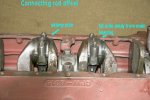
Rods 2 and 3 with correct offset. Fat side away from nearest main bearing.
28
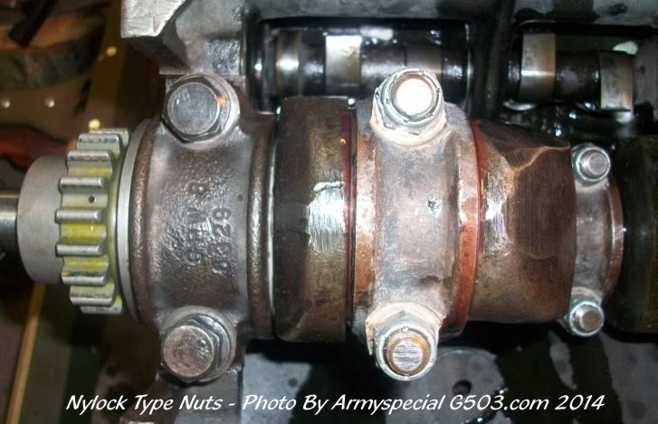
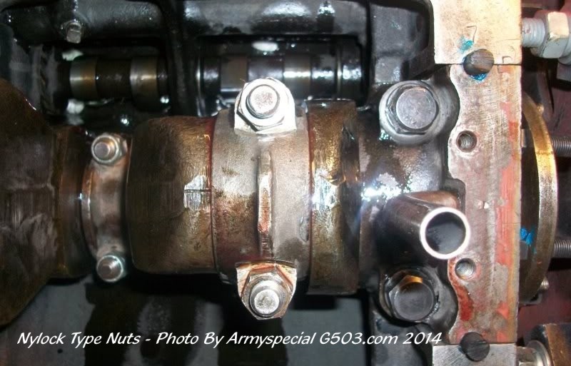
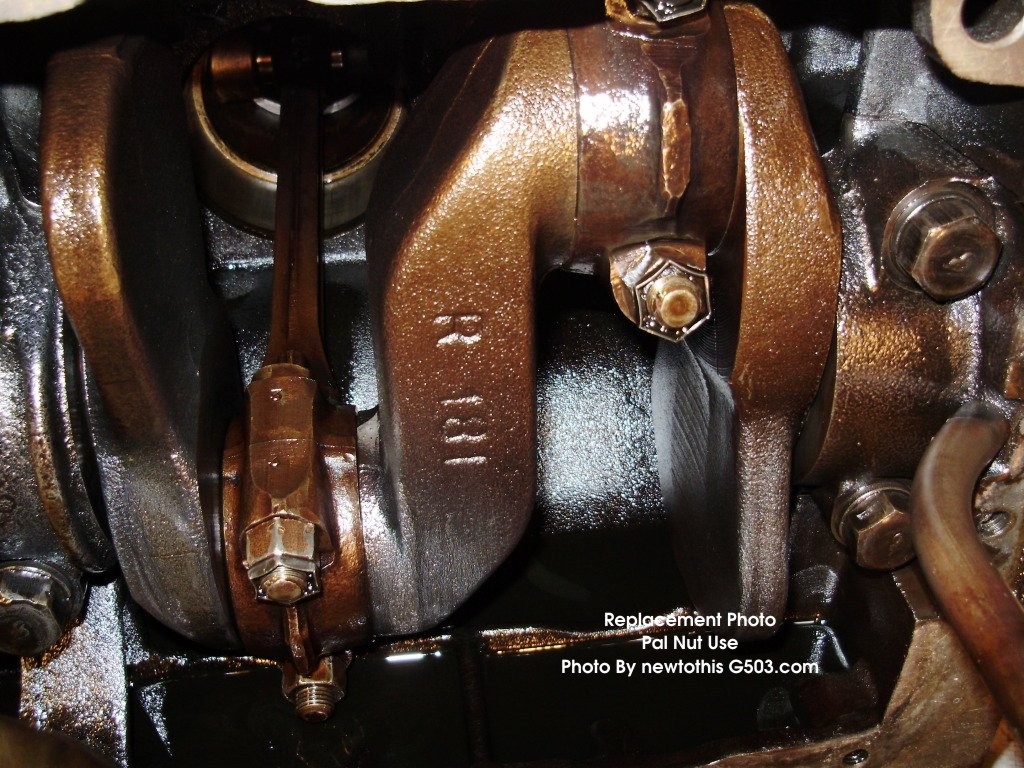
MISSING PHOTOS 28 Substituted
These connecting rod bolt nuts are the split locking kind. If you have a
plain hex nut, you should use the PAL nuts.
29
MISSING
PHOTO
I put this picture of using the torque wrench in to show that the engine
must be secure whether on a bench or on a stand…it will tip over.
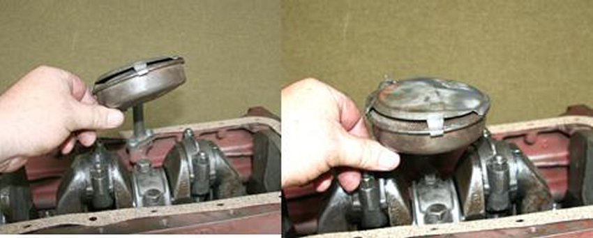
30

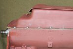
Clean the float well, install gasket and tighten it down, and check that it
doesn’t hit crank in any position.
31
Put the pan on.
I appreciate the nice comments on earlier posts, but I can’t be the only
G503’r that rebuilds engines? Others must have tricks or short cuts or
better ways? I put this out to learn as well as show new people. Is this the
way you do it? I will post the costs later, but what do others do- send it
out? I’m sure others besides myself would like to know. It is a forum.
Thank you, John
Home
John Barton's Engine Rebuild 1
2
4 g503.com
|