|
RESTORATION (1) '44 FORD GPW
Frame & Body
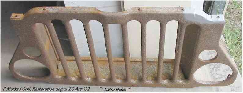
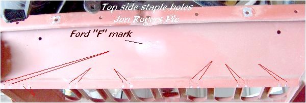
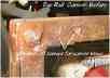
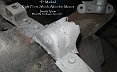
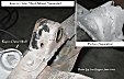
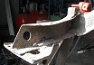
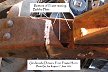
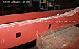
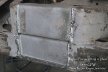
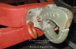
GRILL. This Ford "F" marked
grill was in relatively good condition, rusty, dented, and with twisted bars,
never the less, better than some I
 have
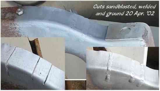
seen. At some stage someone had made three cuts with a hacksaw and folded in a
section of the lower right side, possibly for a forward steering box. After a
light sandblast, I straightened out the folds, and welded them together with the
Oxy. I then spent the next few hours sandblasting the complete grill, noting
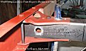
holes, cracks and dents as I went.. One particular crack, shown welded up in the
picture on the left went
from the edge to within a half inch (12.7mm) of the head light opening, In all
there were six similar cracks, one hole for the wiring harness was enlarged on
the top air deflector sheeting, so I put a heavy ring of weld around that, it
should dress up OK when I start playing with the file and grinder. You have
seen. At some stage someone had made three cuts with a hacksaw and folded in a
section of the lower right side, possibly for a forward steering box. After a
light sandblast, I straightened out the folds, and welded them together with the
Oxy. I then spent the next few hours sandblasting the complete grill, noting
holes, cracks and dents as I went.. One particular crack, shown welded up in the
picture on the left went
from the edge to within a half inch (12.7mm) of the head light opening, In all
there were six similar cracks, one hole for the wiring harness was enlarged on
the top air deflector sheeting, so I put a heavy ring of weld around that, it
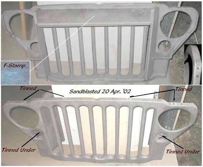
should dress up OK when I start playing with the file and grinder. You
 may
notice in the pic the soldered areas around the bolt holes for all the earthing
straps. As I sandblasted some of this solder away, I'll re-solder those before
masking them off and painting. Note though, the later models had soldered areas
masked off with torn off strips of masking tape, appearing to be square or
rectangular after painting, yet the soldered areas are relatively circular in
appearance, whereas on the earlier models , like Al's '42 GPW, the soldered
areas appear round after painting. This also applies to other soldered areas on
the inside of the fenders. may
notice in the pic the soldered areas around the bolt holes for all the earthing
straps. As I sandblasted some of this solder away, I'll re-solder those before
masking them off and painting. Note though, the later models had soldered areas
masked off with torn off strips of masking tape, appearing to be square or
rectangular after painting, yet the soldered areas are relatively circular in
appearance, whereas on the earlier models , like Al's '42 GPW, the soldered
areas appear round after painting. This also applies to other soldered areas on
the inside of the fenders.
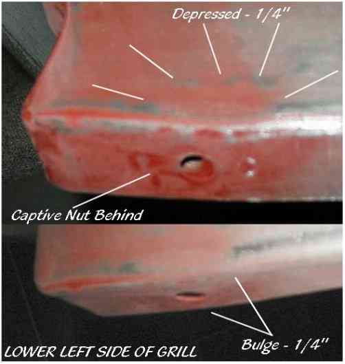
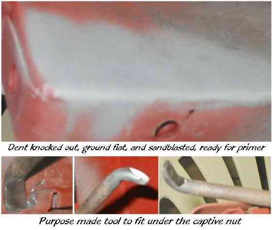
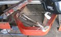
One dent that is causing me a problem is on the lower left front,
a 1/4" deep dent with a 1/4" bulge right smack above the same
location of a captive nut, making it near impossible to tap it out from the
rear. I'm considering drilling a hole and heating the area, and pulling the dent
up and at the same time tapping in the side. This should bring the panel back in
line. Failing that I could always remove the captive nut, panel out the dent,
and reinstall the nut cage, as I have several others where I have to replace
missing nuts. (UPDATE)
Having thought about
it , I decided to make a tool to fit under that captive nut, so I could tap it
down, and it worked. I used an old screwdriver with a broad tip, heated the end,
and bent it in the vice, then ground it to fit, this allowed me to hammer
downwards and right up to the edge of the fold. I then ground off the small
raised areas flat and sandblasted the area ready for primer.
For those who intend to follow this type of repair, if I were to do his job
again, I'd make the tool wider so that there would be fewer marks on the
opposite side. reinstall the nut cage, as I have several others where I have to replace
missing nuts. (UPDATE)
Having thought about
it , I decided to make a tool to fit under that captive nut, so I could tap it
down, and it worked. I used an old screwdriver with a broad tip, heated the end,
and bent it in the vice, then ground it to fit, this allowed me to hammer
downwards and right up to the edge of the fold. I then ground off the small
raised areas flat and sandblasted the area ready for primer.
For those who intend to follow this type of repair, if I were to do his job
again, I'd make the tool wider so that there would be fewer marks on the
opposite side.
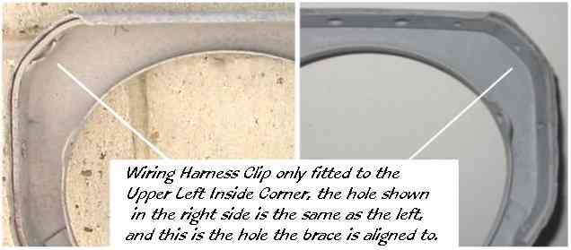
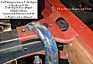
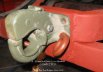
An interesting thing I've found was the left front headlight
wiring loom clip brace, broken off inside the grill edge. I measure mine as 16g,
and 1/2" to 5/8"
 wide,(
Hard to tell with the weld, the remaining part has a hole which matches
with a predrilled hole in the grill edge reinforcing bracing. I posed a question
on the G503 Technical Board about this and was surprised to find that wide,(
Hard to tell with the weld, the remaining part has a hole which matches
with a predrilled hole in the grill edge reinforcing bracing. I posed a question
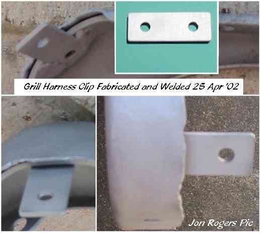
on the G503 Technical Board about this and was surprised to find that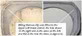 Ford and Willys differ in some respects. Most have been measured at 5/8" wide, the overall lengths vary, from 1.625" to
1.75" and the distance the hole from the ends varies accordingly. For this
particular grill I'll be replacing mine with a 5/8" x 1.750" (15.9mm x 41.3mm) x
16gauge.After fixing the grill, I'll follow up the different measurements that
are being sent to me about the missing brace. My thanks to Steve, Mark, Joe and
Chup for their interest in this subject. Their names will be going on the
combined drawing of the Willys and Ford tabs. In the meantime, I've drawn
the Ford type, sorting out the variables between
that and the Willys may take a while longer. I suspect that the very early
Willys grills will be the same as the Ford as
Ford and Willys differ in some respects. Most have been measured at 5/8" wide, the overall lengths vary, from 1.625" to
1.75" and the distance the hole from the ends varies accordingly. For this
particular grill I'll be replacing mine with a 5/8" x 1.750" (15.9mm x 41.3mm) x
16gauge.After fixing the grill, I'll follow up the different measurements that
are being sent to me about the missing brace. My thanks to Steve, Mark, Joe and
Chup for their interest in this subject. Their names will be going on the
combined drawing of the Willys and Ford tabs. In the meantime, I've drawn
the Ford type, sorting out the variables between
that and the Willys may take a while longer. I suspect that the very early
Willys grills will be the same as the Ford as Ford made the first few batches for Willys probably up until about June of '42.
And contrary to the belief of Chrysler, Ford designed the jeep grill. After making the tab, I inserted an old drill bit into
the hole and located the hole in the grill reinforcing rib, this held the tab in
place while it was being welded. So simple, from start to finish it took 25
minutes. A light sandblast and it's now ready to be primed.
Ford made the first few batches for Willys probably up until about June of '42.
And contrary to the belief of Chrysler, Ford designed the jeep grill. After making the tab, I inserted an old drill bit into
the hole and located the hole in the grill reinforcing rib, this held the tab in
place while it was being welded. So simple, from start to finish it took 25
minutes. A light sandblast and it's now ready to be primed.
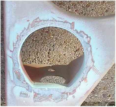
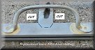
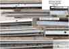
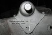
 The
next job will be the openings for the black out marker lights. There were
two plates welded over the openings, and onto these were fitted two round
traffic indicators, I removed the plates some time ago but had never cleaned off
the welds and the edges of the openings. Shown here with some blue spray to show
up the weld edges. After grinding off the bulk of the welds, I'm now using a
small fine file to take the edges back to the correct shape. I should have this
part done within the next few days. The
next job will be the openings for the black out marker lights. There were
two plates welded over the openings, and onto these were fitted two round
traffic indicators, I removed the plates some time ago but had never cleaned off
the welds and the edges of the openings. Shown here with some blue spray to show
up the weld edges. After grinding off the bulk of the welds, I'm now using a
small fine file to take the edges back to the correct shape. I should have this
part done within the next few days.
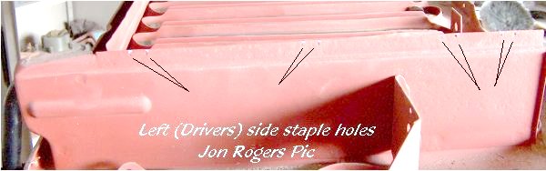
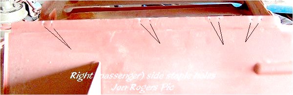
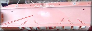
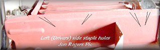
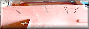
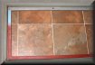
Staple holes for the felt were
placed at random.
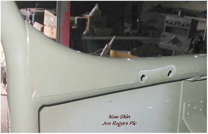
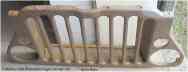
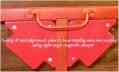
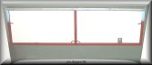
WINDSHIELD
Having looked
around for a few years since picking up the tub which came with a slat grill w/s
frame that
 was totally rusted out, and hearing about the problems with the Repro
inners and outers, I decided it was was totally rusted out, and hearing about the problems with the Repro
inners and outers, I decided it was  worth the wait to get an original,
regardless of condition. I managed to pick up both at the Brisbane Swap Meet in
2001. The outer frame had been re-sheeted, an excellent job, and the frame needs
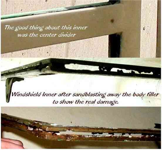
no more than a few small touchups to complete, however, the inner while it
looked good with the paint covering, once sandblasted showed it was too far gone
to restore. This was an early type with the straight handle. So worth the wait to get an original,
regardless of condition. I managed to pick up both at the Brisbane Swap Meet in
2001. The outer frame had been re-sheeted, an excellent job, and the frame needs
no more than a few small touchups to complete, however, the inner while it
looked good with the paint covering, once sandblasted showed it was too far gone
to restore. This was an early type with the straight handle. So
 Sean
Elliott obtained Sean
Elliott obtained
 another one which I combined with the first to make another one which I combined with the first to make
 one decent one.
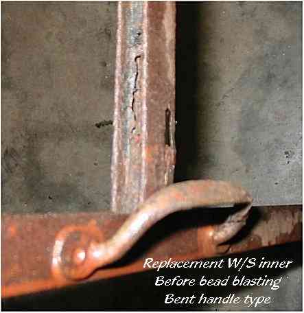
The center section of the replacement inner was shot, and totally rusted out,
however the main part, the outer edge was in a relatively good condition. The
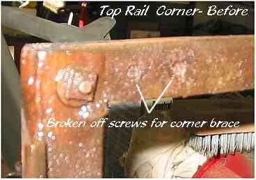
corner frame casts were still in place, although the screws were broken off
inside, this meant that I would have to drill them out from both side to allow
the cast to be withdrawn. As there was no glass in this frame I used a
little heat from a propane torch and the top rail was freed from the bottom. one decent one.
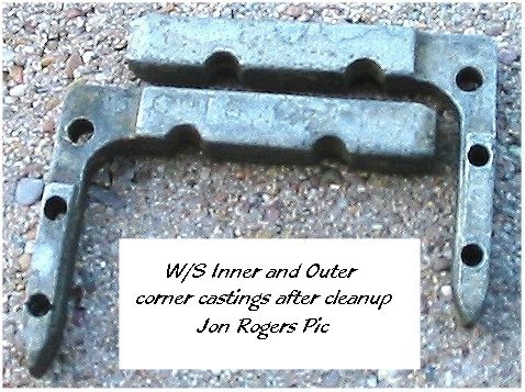
The center section of the replacement inner was shot, and totally rusted out,
however the main part, the outer edge was in a relatively good condition. The
corner frame casts were still in place, although the screws were broken off
inside, this meant that I would have to drill them out from both side to allow
the cast to be withdrawn. As there was no glass in this frame I used a
little heat from a propane torch and the top rail was freed from the bottom.


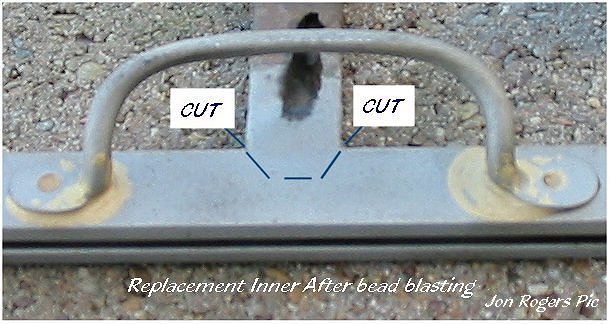
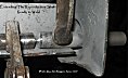
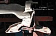
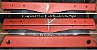
Testing fit of replacement center
section, Welded , and finished, no filler required.
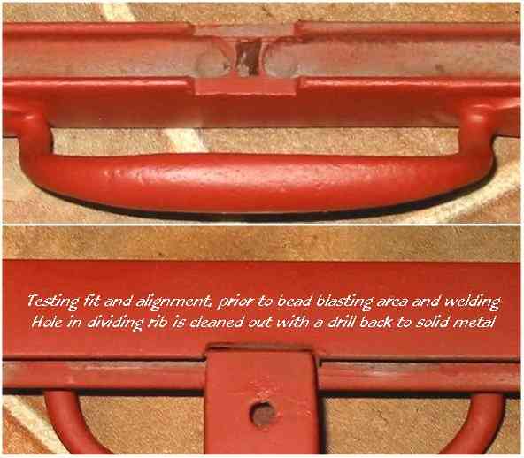
I sandblasted the inner and cut the center section away, primed
the complete thing, as I could sand blast anywhere I needed to weld, filed
the frame down to good rust free steel, measured what length I needed to make
the replacement divider, cleaned that up and drilled out a small rust hole(
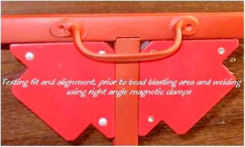
shown in the top left pic) back to good steel. Using magnetic clamps , the
joint was first tack welded and then after checking the alignment, a solid weld
was applied, the weld was ground back, then filed to shape. The alignment was
rechecked and found to be almost perfect, a little heat and the center was
brought back from the 3mm error ( it was leaning back) and primed.. If you
intend to do a similar repair, I can't stress enough the necessity of keeping
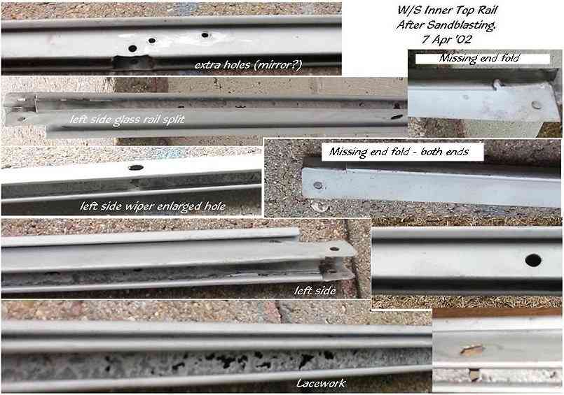
everything in alignment and square. The next part was the Top Rail.


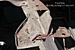
Top Rail after sandblasting, welded
up "Mirror Holes", Wiper Bushes fitted, Channel "lacework" repaired and primed.
I sandblasted the top rail and what I though would be relatively
easy to repair turned out to be a little difficult, but not impossible. The
sandblasting showed up the cracks, and the rust lace work for most of the
channeling length, missing hinge rolls , split ends, extra drilled holes, it was
warped and twisted, but all original and this is what I wanted. I began with
straightening and removing the warp, then tested the fit to the outer frame
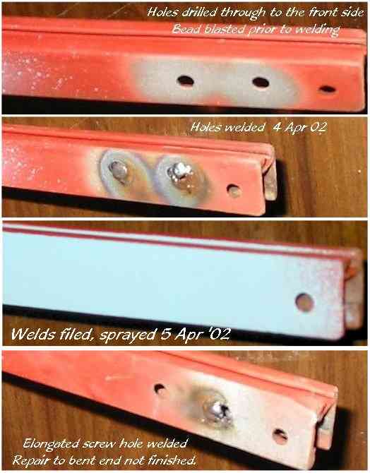
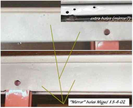
hinge, it slipped in without any problems. Next came the extra holes that had
been drilled , possibly for an inside rear view mirror, these went all the way
through, and was a simple matter of using a mig welder, grinding the weld and
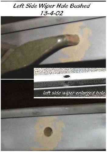
filing back to shape. Next was the oversized holed that had been
drilled/gouged/worn/butchered for the wiper arm shafts, one was 3/8" and the
other was over 1/2" in diameter. I found two brass fittings with a 1/4" bore,
the right length of around 5/8", I ground off the hex head, and using a 1/4"
drill shaft rotated them on the bench grinder, this "turned" them down to 1/2"
diameter. I filed the holes in the inner to even them up, inserted the bushes
and brazed them into position, a quick grind and file and the inner started to
take on a respectable look. One end was split for about 8" from the end, I
inserted the cast corner frame brace, and inserted a shim under that to give me
clearance for paint later one. Then using the flat edge of a 1/4 x 1" flat
steel, tapped the channel fold square and even. Using the oxy I brazed
welded full length of the split and with the 4" grinder, with a new disk
attached, on edge I carefully ground
down the brazing to leave a smooth layer of brazing holding everything together.
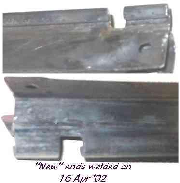
When Sean brought up the replacement inner he included an extra top rail, so I
used this to repair the missing end hinge folds. Cutting the "new" pieces from
an old top rail, up close to the fold of the top and front edge, I filed away
the corner and fitted the new pieces, then it was a simple  matter of oxy matter of oxy
 welding
the pieces in, held in place with magnets. It was necessary to file away the
weld penetration so the cast corner braces slide in and out and the hole for the
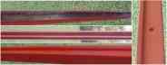
corner screw lines up, and a little dressing of the welds on the outside. The
pic on the right is after applying the primer/putty, 99% of this was removed in
the rub down stage, leaving only sufficient to cover the edges of the welds, and
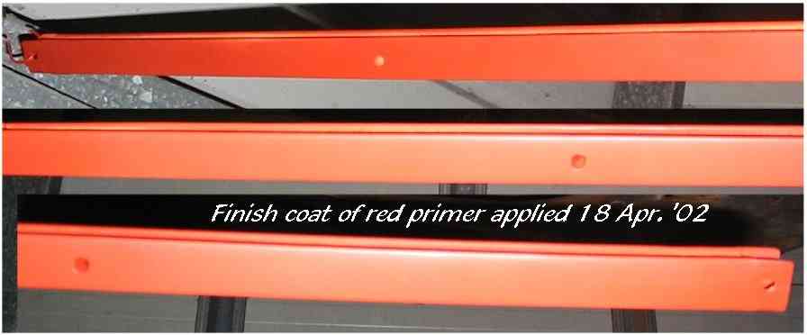
other small rust pits. The final application of red oxide primer was then
sprayed on. I'll leave it primed until I have the glass cut and test fitted. welding
the pieces in, held in place with magnets. It was necessary to file away the
weld penetration so the cast corner braces slide in and out and the hole for the
corner screw lines up, and a little dressing of the welds on the outside. The
pic on the right is after applying the primer/putty, 99% of this was removed in
the rub down stage, leaving only sufficient to cover the edges of the welds, and
other small rust pits. The final application of red oxide primer was then
sprayed on. I'll leave it primed until I have the glass cut and test fitted.
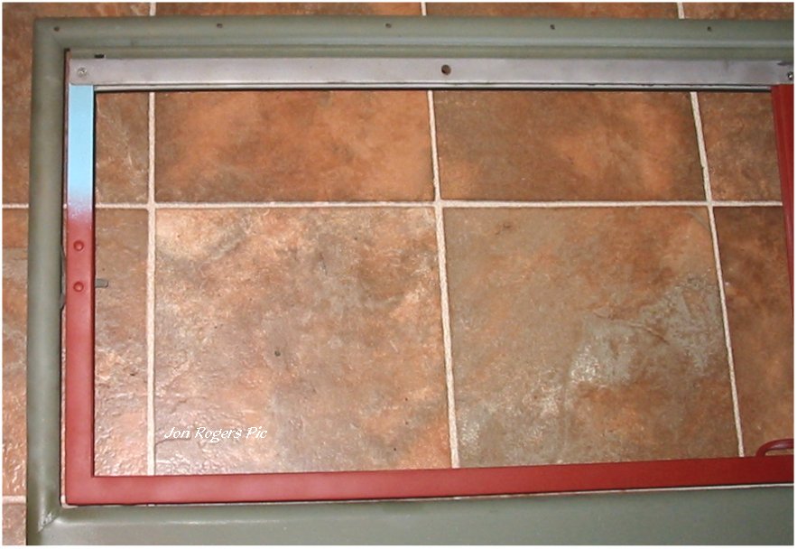
Friday, 26 APRIL 2002 The
ordered Glass for the Windshield arrived at 6.45pm, cut to 23" x 12.5" (x2), the
Autoglazier delivered them to the door, we test fitted to the frame, on first
inspection all appeared well, and I wrote out the cheque for AU$59.40( which
included the G.S.T. of 10%) so I was extremely pleased at the price. The
following day I checked the fit once more in the frame and found that on one
side the top rail was touching the glass which would not allow for any sealant,
my immediate thought was I had somehow made a mistake when repairing the inner
frame. After rechecking the internal measurements and the frame for square, I
then checked the glass and found that one piece was out of square, and wider on
one end than the other. On Monday I took the glass to the local glass shop where
the edge was re-ground back to square and size, retested the fit and it was
perfect, the regrind cost AU$5.... cheap!. Over the weekend I had done up a dxf
file on the computer of the Ford W/S Safety Glass logo, and on Monday, had the local
sign shop cut me some sticky back stencils, 12 logos on one sheet, AU$10, and
did a test on some glass I had in the shed. The principal of using
the computer of the Ford W/S Safety Glass logo, and on Monday, had the local
sign shop cut me some sticky back stencils, 12 logos on one sheet, AU$10, and
did a test on some glass I had in the shed. The principal of using
 a
vinyl stencil ( Old Henry used stamped 35mm Film) and sandblasting ( same as
Henry did back in the 20's, 30's and 40's), the first test showed that with too
much pressure I blew through the stencil and scored the glass, also the sharp
edges of the stencil were lost, ( Pic on the top right) so on the second test I used lower
pressure and kept the blaster at a distance of 150mm (6") this gave me better
control and an even etch. (Left Pic). a
vinyl stencil ( Old Henry used stamped 35mm Film) and sandblasting ( same as
Henry did back in the 20's, 30's and 40's), the first test showed that with too
much pressure I blew through the stencil and scored the glass, also the sharp
edges of the stencil were lost, ( Pic on the top right) so on the second test I used lower
pressure and kept the blaster at a distance of 150mm (6") this gave me better
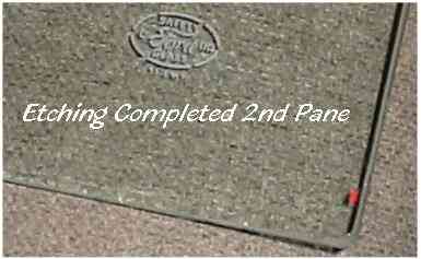
control and an even etch. (Left Pic).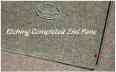 It took about an hour to remove the
unwanted vinyl from the first pane stencil , but only 30 minutes to do the
second, both panes were blasted, and they turned out far better than I had
hoped, and looked original, which after all was the main objective of the
exercise. I don't recommend this method unless you have the patience to sit with
a magnifying glass and a sewing tool called a "Quick Unpick" which I found to be
better than an "Exacto" knife for the removal of the waste vinyl. The
location of the logo can be found in the All American Wonder Vol.2, don't forget
to add extra to the measurements for the glass which fits inside the frame if
you are doing this to glass not yet fitted. It took about an hour to remove the
unwanted vinyl from the first pane stencil , but only 30 minutes to do the
second, both panes were blasted, and they turned out far better than I had
hoped, and looked original, which after all was the main objective of the
exercise. I don't recommend this method unless you have the patience to sit with
a magnifying glass and a sewing tool called a "Quick Unpick" which I found to be
better than an "Exacto" knife for the removal of the waste vinyl. The
location of the logo can be found in the All American Wonder Vol.2, don't forget
to add extra to the measurements for the glass which fits inside the frame if
you are doing this to glass not yet fitted.
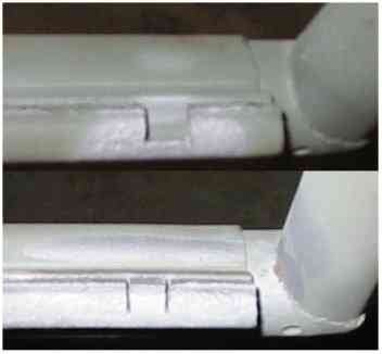
Monday 6 May 2002, The outer
hinge roll of the top tube of the outer frame was missing the locking tabs, also
a short
 length
from one end. Inspecting the roll I saw that 1/8" was folded back on itself, and
tightly crimped. So grabbing a length of 18g I folded over the 1/8" and cut
short strips to match the wide of the holes, these were welded in place, the
excess weld filed off and the slots cut with a hacksaw, similar to the original,
even down to the different depths I found. The area was then lightly sandblasted
to give a bond for the primer. length
from one end. Inspecting the roll I saw that 1/8" was folded back on itself, and
tightly crimped. So grabbing a length of 18g I folded over the 1/8" and cut
short strips to match the wide of the holes, these were welded in place, the
excess weld filed off and the slots cut with a hacksaw, similar to the original,
even down to the different depths I found. The area was then lightly sandblasted
to give a bond for the primer.

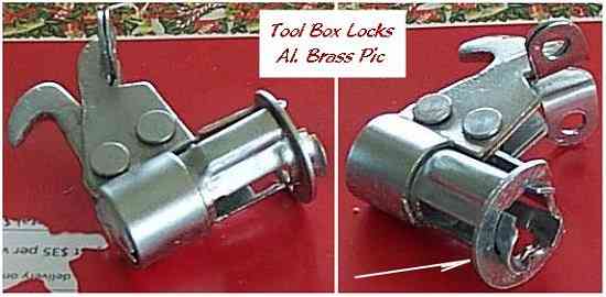
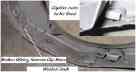
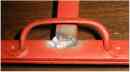
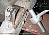
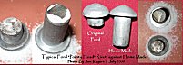
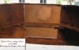
TOOL BOX LOCKS Just before going over to see Al in November, I removed the
tool box l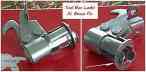 ocks from the GPW, they looked pretty rough. One was missing the
locking tab for the lock barrel, but this wasn't a problem, Al has some 18g
plate handy in his garage. I set about making a new one the morning we took them
to the electroplaters ( The "new" tab is arrowed on the right side of the pic
45K). The barrels , once cleaned up, look like new, although , they do show some
wear around the key hole. ocks from the GPW, they looked pretty rough. One was missing the
locking tab for the lock barrel, but this wasn't a problem, Al has some 18g
plate handy in his garage. I set about making a new one the morning we took them
to the electroplaters ( The "new" tab is arrowed on the right side of the pic
45K). The barrels , once cleaned up, look like new, although , they do show some
wear around the key hole.
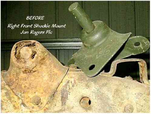
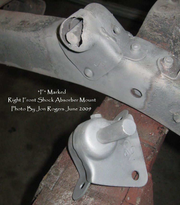
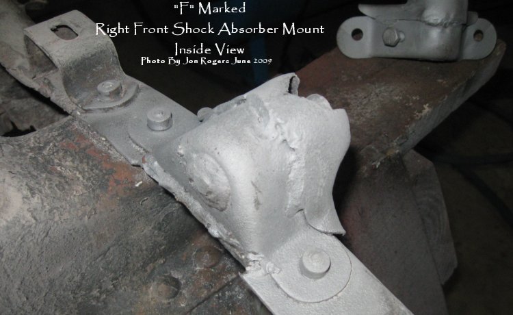
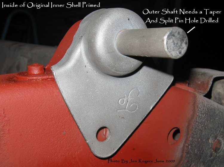
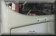
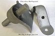
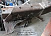
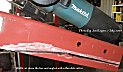
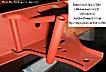
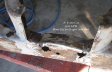
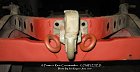
FRAME/CHASSIS There's several sections of the frame that need serious work
done, one is the Right Front Shock Mount. I
 purchased
an F marked replacement from
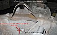
Marathon Spares in Tamworth. Some things to note on
these reproduction mounts, there's no hole drilled for the split pin on the
shaft, and there's no hole or captive nut on the front face for attaching the
earth strap bolt. My most likely method of repair is to cut the old mount
through just under the shaft bulge, and weld the altered repro so I can keep the
original rivets. Two factors purchased
an F marked replacement from
Marathon Spares in Tamworth. Some things to note on
these reproduction mounts, there's no hole drilled for the split pin on the
shaft, and there's no hole or captive nut on the front face for attaching the
earth strap bolt. My most likely method of repair is to cut the old mount
through just under the shaft bulge, and weld the altered repro so I can keep the
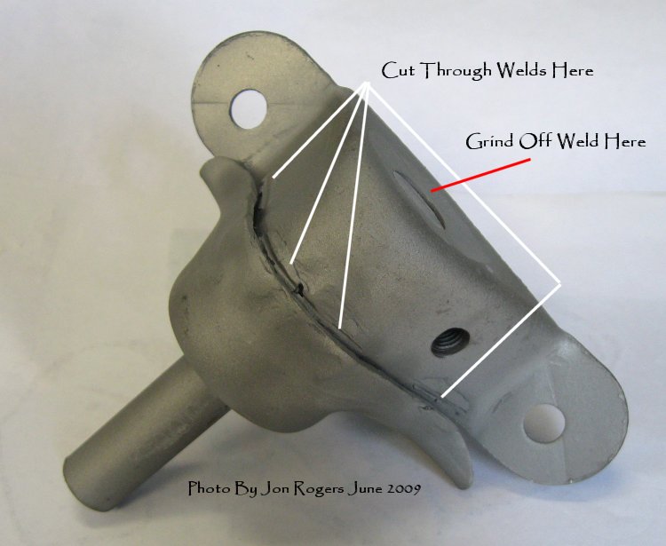
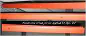
original rivets. Two factors that may influence the decision are, the
Philippine steel is renown to be the worst steel in the world to weld, and the condition of
the original component after bead blasting. (UPDATE 15
April 2002) As the steel is so poor, I decided to braze the nut into
position. After sandblasting the mount, I also found that the welds holding the
two pieces together will need redoing, as they are porous and thin. that may influence the decision are, the
Philippine steel is renown to be the worst steel in the world to weld, and the condition of
the original component after bead blasting. (UPDATE 15
April 2002) As the steel is so poor, I decided to braze the nut into
position. After sandblasting the mount, I also found that the welds holding the
two pieces together will need redoing, as they are porous and thin.
(Updated June 2009). Finally decided to tackle this
job which I think is a little harder to do than the rear cross member and
A-Frame I just completed. First thing was to see what I was dealing with
in regards rust and available metal left on the original. Wherever
possible I'll keep as much of the original parts of the frame and tub,
using either reproduction or home made repair sections. I tossed out the
idea of using the complete reproduction mount......Started 23 June
2009
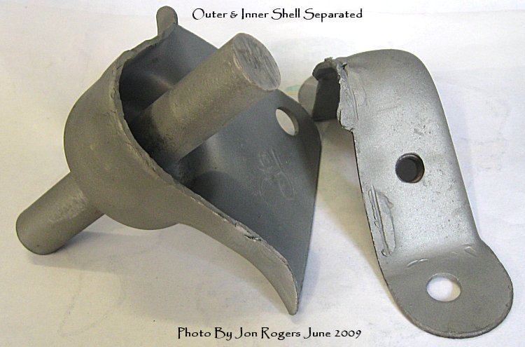
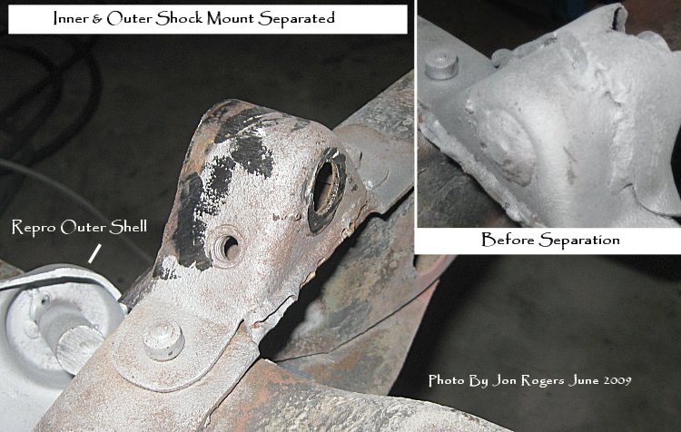
Step 1. Seeing what I have

Step 2. Separating the
Reproduction Shell Halves.


Step 3. Separating the Original
Shell Halves
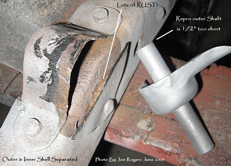
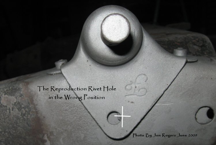
What's
irking me at the moment is the repro front shock mount, the shaft is too
short when you separate the two shell halves so it doesn't fit the inner
shell of the original, ALSO........and
what's more important....is the rivet hole is in the wrong
place.
I'll either have to replace the shaft or extend it that 1/2" so it
will fit.
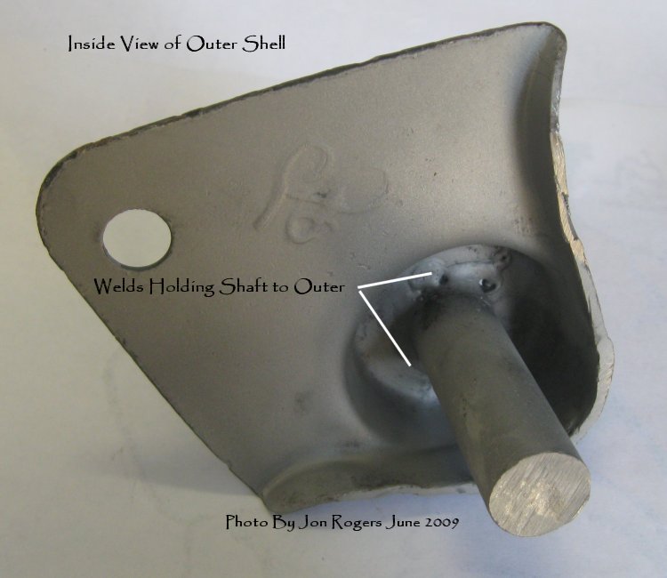
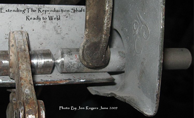
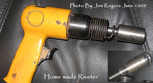
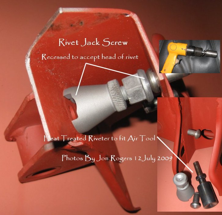
Step 4. Decided to extend the
shaft , remove all of the original outer bracket, including the rivet.
Will now need to weld up the misaligned hole in the reproduction outer and
re-drill to align with the hole in the frame. Made a riveter for my air
chisel. If it works, fine, if it
doesn't, I'll try something else.


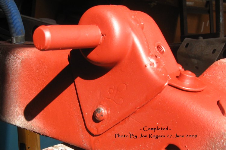
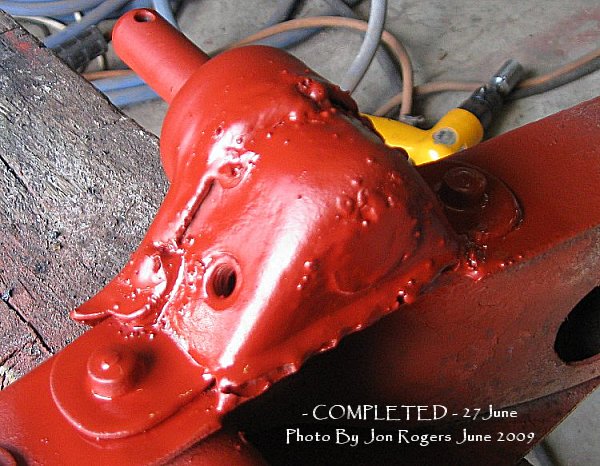
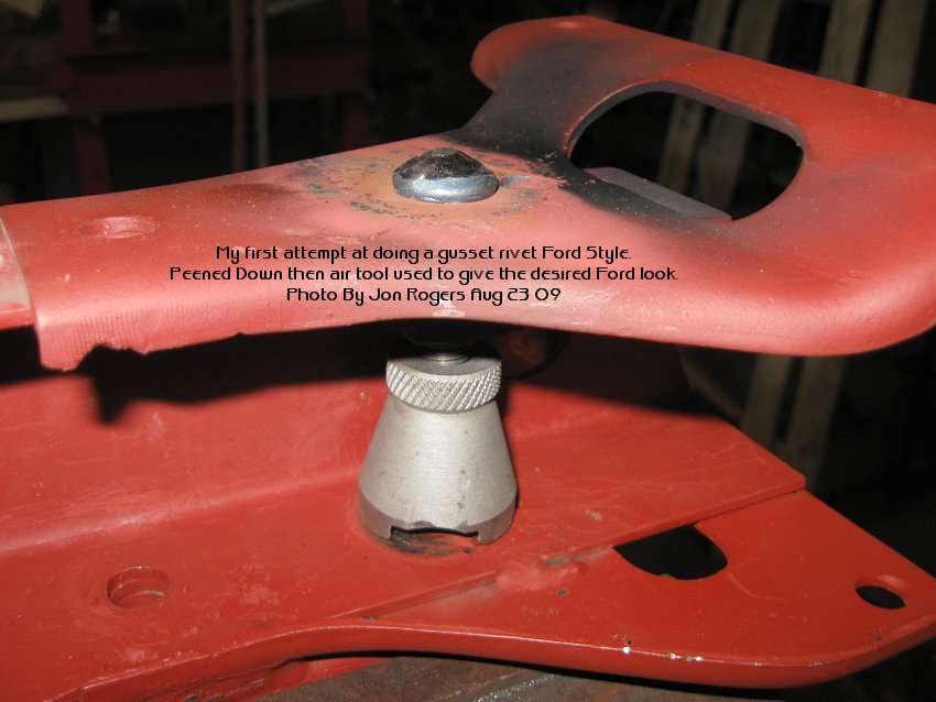
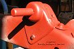
The riveter worked....... in a
fashion....the end isn't like the Ford, too rounded, so later I may go
back and try again, in the meantime, it's holding, and looks a lot better
than I started with.Hole drilled for the split pin, end of the shaft
tapered, Inner and Outer joined with an arc welder, so look like the same
crappy welds that were there originally. I'm happy with it. This
of course will be mostly covered by the battery tray when everything goes
back together.
- COMPLETED - 27 June 2009 -

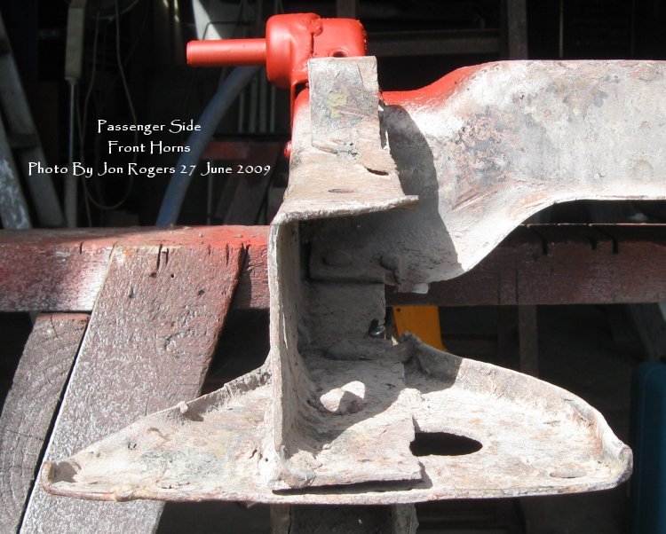
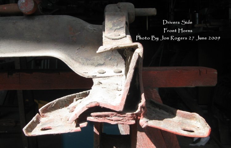
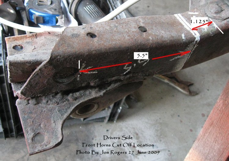
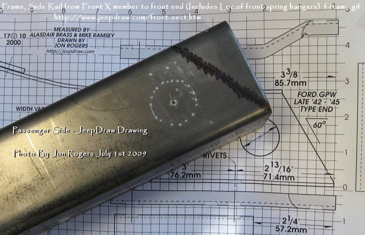
Next job:- Started 27 June 2009
is the two front frame
ends, another fun job coming up!

There's really one way to do
this repair, remove everything from 1.125" forward of the front edge
of the radiator bracket, which also aligns with 5.5" to the rear
measured from the rearwar edge of the hole in the frame side. This will
give me measurements for when I replace the front horns.

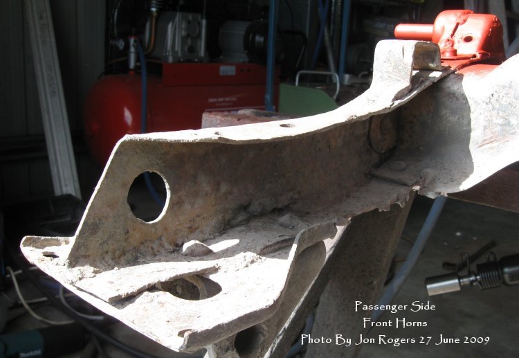
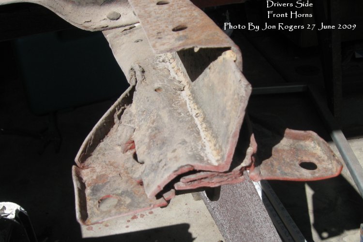
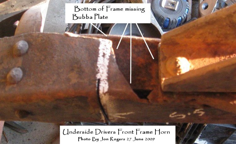
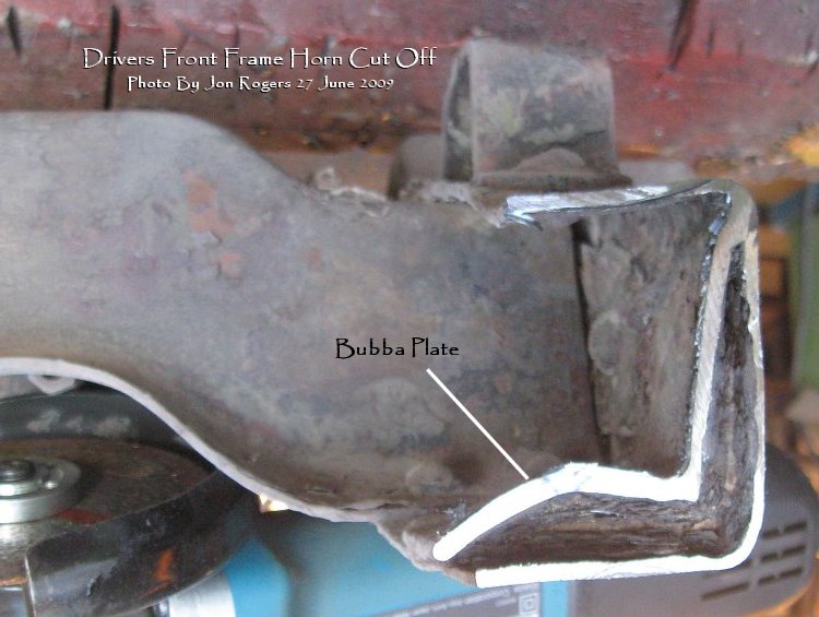
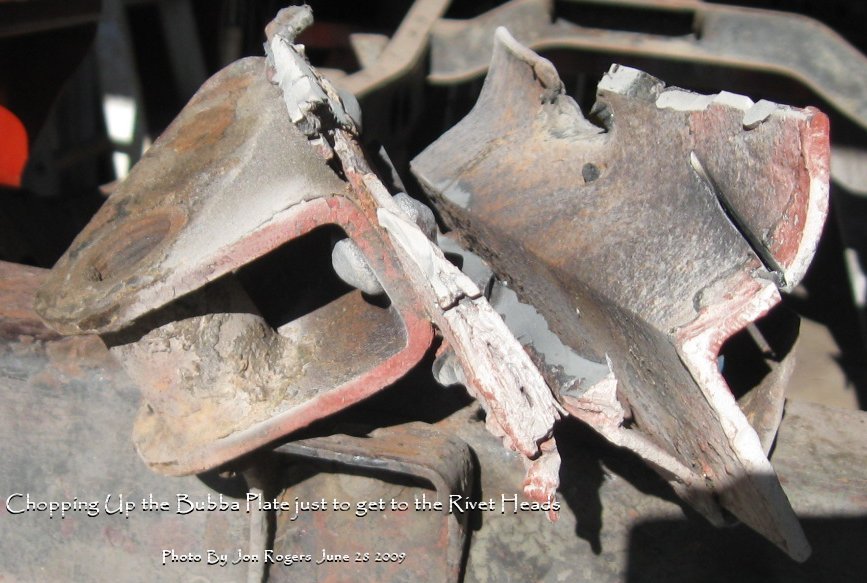
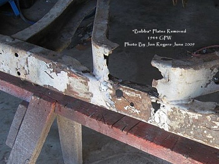
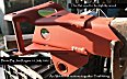
As I wanted to re-use the
Spring Mounts, I had to cut away all the Bubba Plates, rust, excess welds,
and 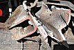 the the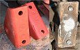 remains of the bumper gusset plates, and boy!. am I pleased I went to the
trouble, the threads are perfect, but the best and biggest surprise was to
see both mounts were "F" stamped. My aim here is to make the
frame sections, then while both ends are off the frame, mount the gussets,
the spring mounts by riveting as per the original, much easier when
they're short pieces. I'll then attach the bumper to the gussets. This
will achieve two things, firstly, the gussets, therefore the frame
pieces, will be at the exact distance apart, secondly, getting the
frame pieces at the same height as they're attached to the bumper I can
make all the measurements and levels so I should, theoretically be welding
the frame ends back in the exact, factory position.
remains of the bumper gusset plates, and boy!. am I pleased I went to the
trouble, the threads are perfect, but the best and biggest surprise was to
see both mounts were "F" stamped. My aim here is to make the
frame sections, then while both ends are off the frame, mount the gussets,
the spring mounts by riveting as per the original, much easier when
they're short pieces. I'll then attach the bumper to the gussets. This
will achieve two things, firstly, the gussets, therefore the frame
pieces, will be at the exact distance apart, secondly, getting the
frame pieces at the same height as they're attached to the bumper I can
make all the measurements and levels so I should, theoretically be welding
the frame ends back in the exact, factory position.
The next step is to fabricate
the frame horns, piece of cake! Here in Australia, it's almost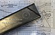
 impossible
to get the correct gauge so you make do with what's available, the steel I
got is only .2mm thicker than the original, so I figured, by the time I
disk sand off the joining welds, it should come back to near enough to be
good enough and undetectable. Paying for one long piece to be folded is
far cheaper than paying for two short pieces, just needed to mark each
end, then split the piece in half. After that it's just a matter of
trimming each piece to suit where I removed the original horns. I should
be able to cut and drill for the rivets this afternoon. And people wonder
why I do the drawings. impossible
to get the correct gauge so you make do with what's available, the steel I
got is only .2mm thicker than the original, so I figured, by the time I
disk sand off the joining welds, it should come back to near enough to be
good enough and undetectable. Paying for one long piece to be folded is
far cheaper than paying for two short pieces, just needed to mark each
end, then split the piece in half. After that it's just a matter of
trimming each piece to suit where I removed the original horns. I should
be able to cut and drill for the rivets this afternoon. And people wonder
why I do the drawings.

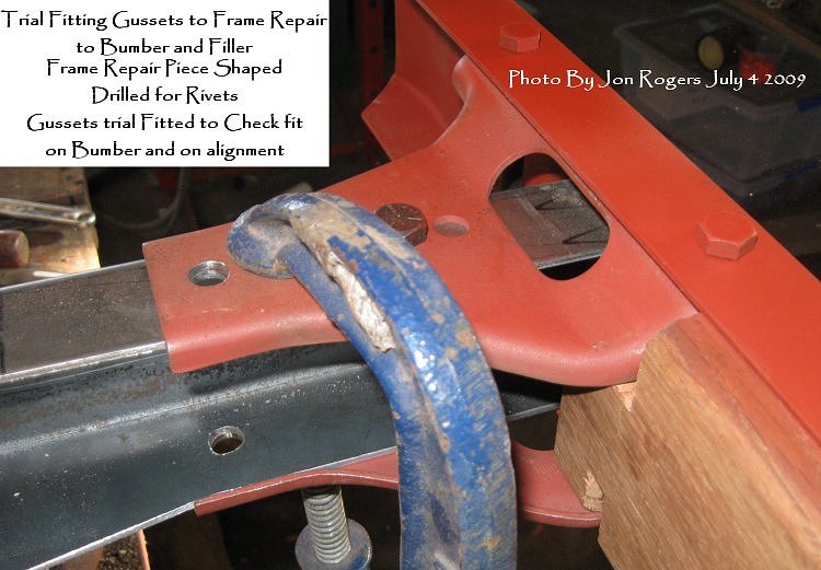
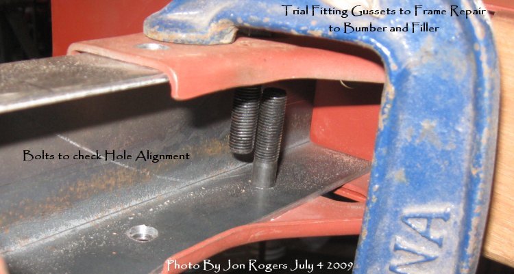
I wanted to make sure the frame
pieces I folded up were at the correct width, that the holes I drilled
were in the correct places, that when the gussets were attached so the
rivet holes aligned, that the gussets fitted within the bumper and that
the whole thing was aligned so top and bottom holes in both the bumper and
the gussets and the wood filler all aligned..whew!That was a mouthful..
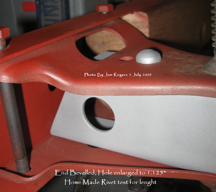
I still need to open the large
hole in the frame repair piece and bevel back that leading edge..
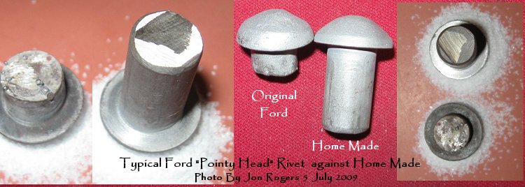
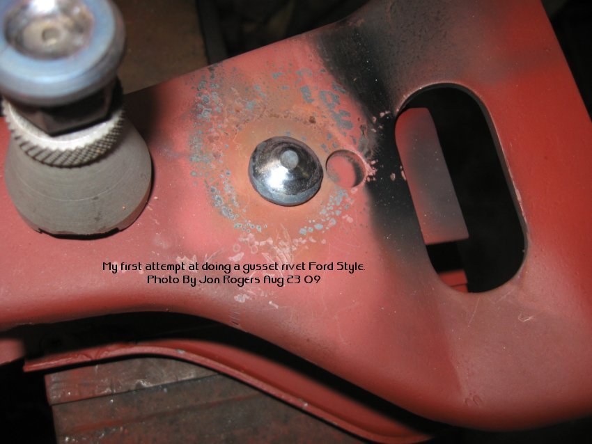
And yes....I intend to use real rivets........should be interesting.....
Decided that as typical Ford
Pointy Head Rivets are not available I'd make my
 own
as I want this area to look as original as possible. And, because the
original size is not available in Australia, I used bolts, first welding
with the Mig to build up the flats of the bolt head, then turning these
down on the lathe until the size matched the original. I'll only know if
this works after I set the rivets, but it's better than the alternative of
using bolts or snap off rivet "look a likes". I hear you ask
"Why go to all that trouble?", the simple answer is....
"Because!" own
as I want this area to look as original as possible. And, because the
original size is not available in Australia, I used bolts, first welding
with the Mig to build up the flats of the bolt head, then turning these
down on the lathe until the size matched the original. I'll only know if
this works after I set the rivets, but it's better than the alternative of
using bolts or snap off rivet "look a likes". I hear you ask
"Why go to all that trouble?", the simple answer is....
"Because!"
The correct length needed is
the total thickness of all material the rivet will go through plus 1.5
times the diameter of the rivet. If you keep to these formulas you'll do
OK for rivet diameter and length. Thanks to Bill for this information.
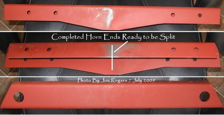
Now that I know the ends fit
the bumper and the bracket holes are in the correct position, I finished
off the horns ready to be split in two. It's far easier to make these
horns when the pieces are together as you have something to fit into the
vise making cutting of the bottom edge easier. If you're considering
making these for yourself, I've added the following photos to show how I
do the cuts in this steel. The marking should be easy to see, I place the
piece so I can see the marked line and then bring the disk cutter up to
the line. This leaves very little to be removed after cutting. I
then, using the disk cutter, grind it flat and smooth, finishing off the
edges with a file . usually making the edge slightly beveled as though it
were cut in a press. When making long cuts, priming the part makes for
easier marking, you can see the chalk and the lines. On the photo to the
bottom left, you can see where I've brought the disk up to the line, I
then make a groove that the disk can run in so it doesn't go spearing off
the line ruining the workpiece.Having the line visable, as you look down
on the workpiece also makes for a better job.
Restoration...It's all about
the illusion.
Once split in two, I can mark
each piece where I want it to fit on each end where I cut off the old
horns. I may need to make the passenger side longer as there's some
pitting and old Bubba grinding grooves on what's left of the frame.
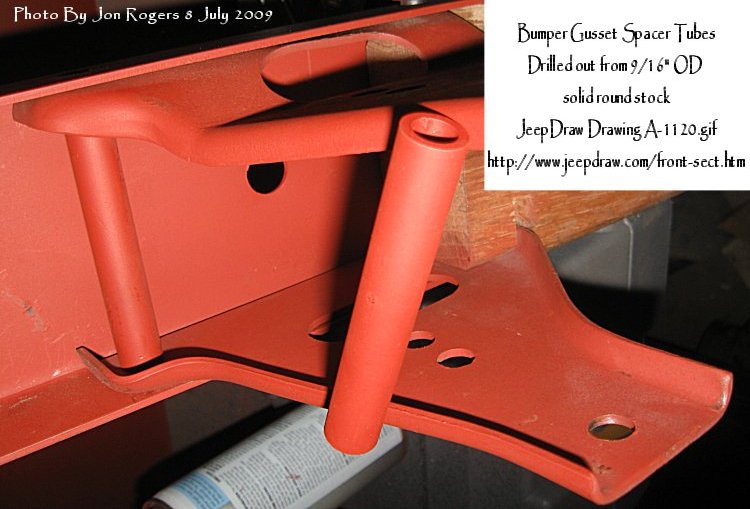
 As
the right size tubing is not available, we're a Metric country, these are
the tubes which separate the gussets inside the bumper and, as all I could
get was 9/16" round solid stock, decided to make the tubes from that.
An hour in the lathe and they were completed. Another small job done. As
the right size tubing is not available, we're a Metric country, these are
the tubes which separate the gussets inside the bumper and, as all I could
get was 9/16" round solid stock, decided to make the tubes from that.
An hour in the lathe and they were completed. Another small job done.
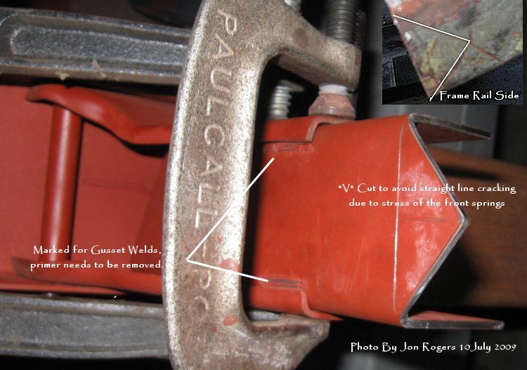
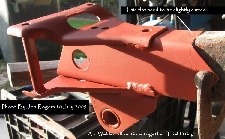
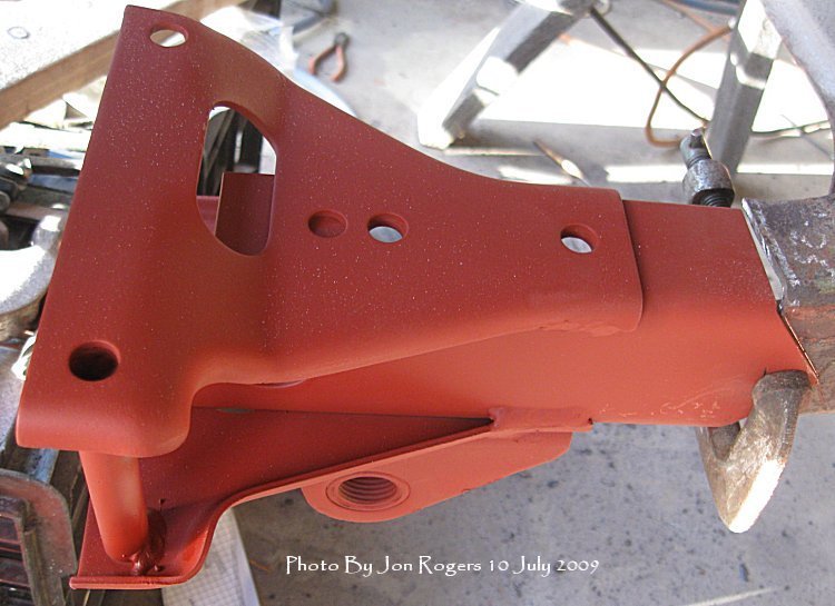
Time came around to putting
everything together before riveting. I decided to scarf join the side
frame rail instead of a straight weld, hopefully, this will give me
greater strength as the front springs are connected to this repair section
and I don't want any nasty surprises. I still need to open up the top flat
of the repair piece to match the beginning of the side rail curve. While
clamped and attached to the bumper so that everything fitted correctly I
arc welded the pieces together, all I need do now is insert the rivets,
set them, cut the frame side rail and weld everything together.


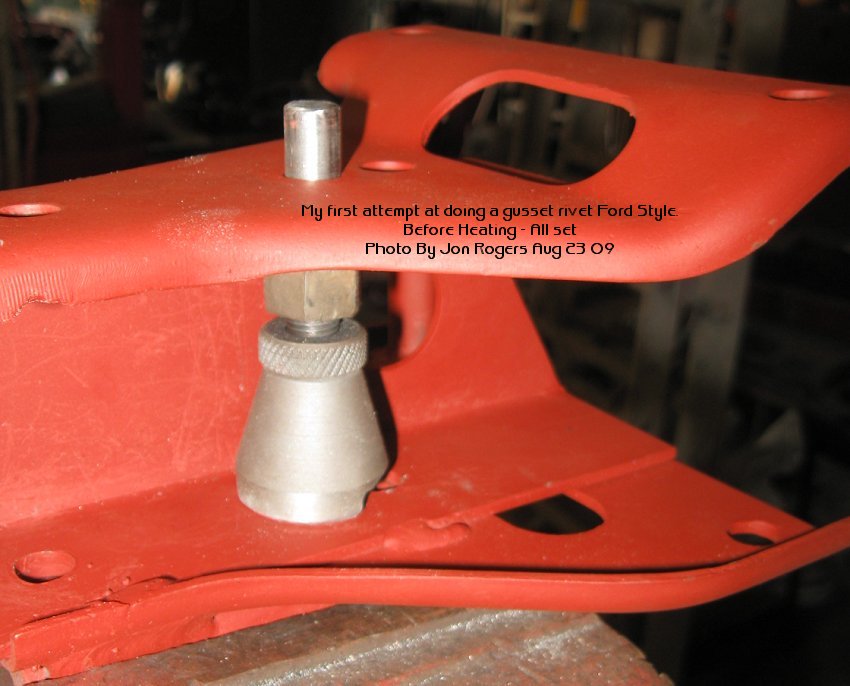
It was far easier than I
thought it would be. After setting the jack, my son Pat, heated the end
until it was a bright red, then, using a ball pein hammer, I proceeded to
form the end. As this was happening, the rivet became tighter in the hole,
especially after hammering straight down with the flat of the hammer. This
really is a two man job, especially when the piece is sitting loosely in
the vice, there's a oxy torch going full steam ahead, and I believe it
would be dangerous if tried alone. It was OK. we actually had fun, and I
got to teach my son a few new words. It was late in the afternoon, so
tomorrow, we'll do it all again.
I couldn't get the rivets I
wanted, although a good mate sent me some from South Australia, Thanks
Mike. I'll 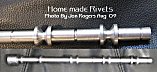 keep
those rivets for the repairs to other parts of the frame. I made the
rivets for this part in the lathe, all in one go, four long and four
short. The short ones for the tops and the slightly longer ones for
underneath where the spring gusset plates are attached. As I need them,
I'll cut them off the "String" with a hacksaw so the heat
doesn't harden them before setting. All in all, I'm pleased with the days
result. keep
those rivets for the repairs to other parts of the frame. I made the
rivets for this part in the lathe, all in one go, four long and four
short. The short ones for the tops and the slightly longer ones for
underneath where the spring gusset plates are attached. As I need them,
I'll cut them off the "String" with a hacksaw so the heat
doesn't harden them before setting. All in all, I'm pleased with the days
result.


FRAME/CHASSIS One of the first shocks I received when I first looked at the
frame was the
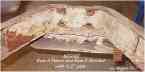 "repair?" someone had done to the A Frame and rear
cross member using 1/2" steel plate. After seeing how a restoration might be achieved on
this, I decided that it would be best to cut the A Frame between the lightening
holes along the A Frame sides, and fabricating a new A section, and at the same
time making a new rear cross member, both relatively easy to do.( See
Parts
and Ed Campions rear cross member) "repair?" someone had done to the A Frame and rear
cross member using 1/2" steel plate. After seeing how a restoration might be achieved on
this, I decided that it would be best to cut the A Frame between the lightening
holes along the A Frame sides, and fabricating a new A section, and at the same
time making a new rear cross member, both relatively easy to do.( See
Parts
and Ed Campions rear cross member)
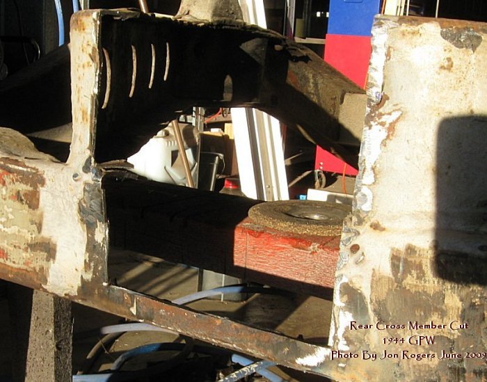
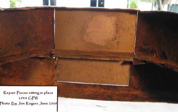
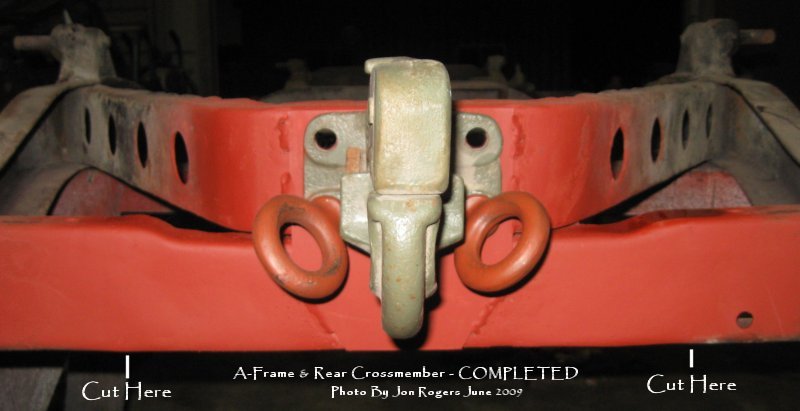
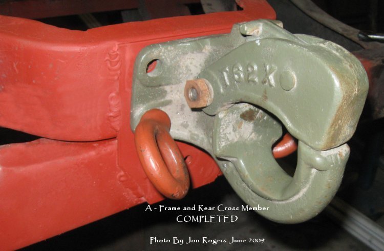
Updated June 2009
Removed the offending Bubba plates,
then the real shock set in, not only was the A-Frame ripped out, but the rear
cross member was cracked right through. A good mate in Melbourne, Bill Mullen
sent me up a section of original Ford A-Frame section, perfectly good for the
purpose, all I had to do was cut out and weld in a circular section and I had
the part for making the repair to the A- Frame. I had some correct gauge steel
to make the missing section of the rear cross member.


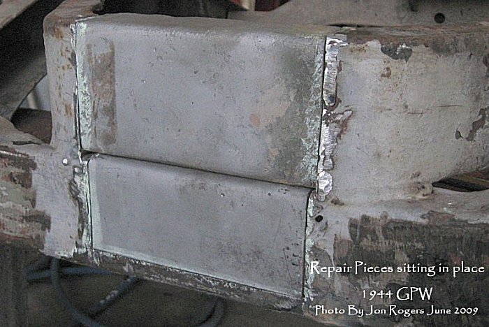
I asked on the Gee about a weld which
was present between the A-Frame and the rear cross member as I didn't think it
should be there. I was right and I wasn't happy about trying to grind out that
Bubba Weld.. so I took to the rear cross member with a thin cut off disk.
This allowed me to fix where I went a little deep with the grinder trying to get
rid of the welds. Really easy to do,
actually it surprised me how quickly it all went back together. The new Mig is
beautiful to use, vertical up welds are a breeze with good penetration and very
little left to grind back to smooth.


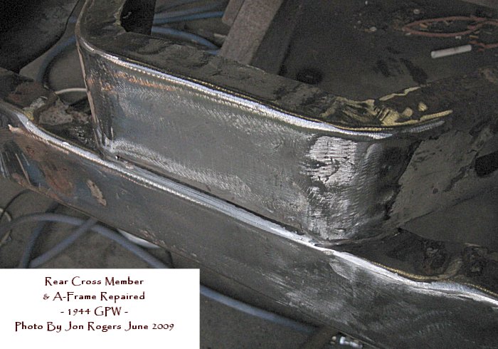
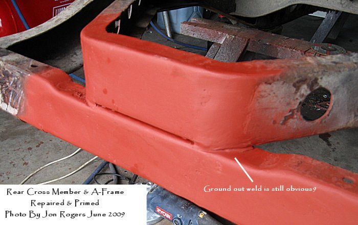
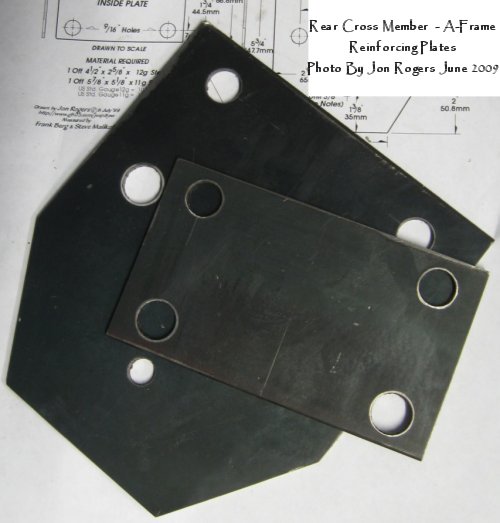
I deliberately did rough welds when
attaching the reio plate to the a-Frame and rear cross member as almost all
original plates were this way. Making the reio plates was dead set easy, 20c
worth of steel, one of my drawings, Rear Section - 5196-5097.gif
and a 4" disk grinder and it was made in half an hour.
REPAIR COMPLETED
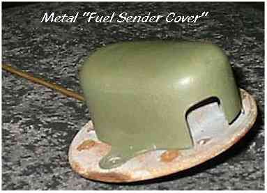
SENDER COVER As mentioned in Nabholtz, for a short period the fuel sender
cover was metal. I was fortunate to get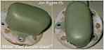
 this one
in excellent condition,( come to think of it, they are extremely rare in any
condition). This one required only superficial restoration. After a short
spell in a container containing brown vinegar, the light rust was dissolved,
then washed, dried, primed and painted. These are now available as repros from Ron
Firzpatrick Jeep Parts this one
in excellent condition,( come to think of it, they are extremely rare in any
condition). This one required only superficial restoration. After a short
spell in a container containing brown vinegar, the light rust was dissolved,
then washed, dried, primed and painted. These are now available as repros from Ron
Firzpatrick Jeep Parts
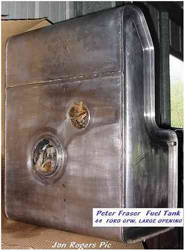
FUEL TANK
 When
I found out that Peter Fraser was leaving Australia to make his home in the
United States, I just had to have one of his fuel tanks before he left. These
are the best reproduction fuel tanks money can buy, made from the correct gauge
and the correct leaded steel, the best part is...They Fit! unlike the other so
called reproductions that are on the market, which do not come near Peters for
quality and value for money. This is the best money I've spent so far on my
restoration. They will be available in the U.S. from
Ron Fitzpatrick on the G503 When
I found out that Peter Fraser was leaving Australia to make his home in the
United States, I just had to have one of his fuel tanks before he left. These
are the best reproduction fuel tanks money can buy, made from the correct gauge
and the correct leaded steel, the best part is...They Fit! unlike the other so
called reproductions that are on the market, which do not come near Peters for
quality and value for money. This is the best money I've spent so far on my
restoration. They will be available in the U.S. from
Ron Fitzpatrick on the G503
Home Restoration
2
3
4
g503.com
|